
Electrical source emission device and control method with soft chopping wave characteristic

A technology of transmitting device and electric source, which is applied in the direction of control/regulation system, output power conversion device, electrical components, etc., can solve the problem of narrowing the duty cycle variation range of step-down chopper and current stabilization circuit, low power density, high-pass State loss and economic cost and other issues

Inactive Publication Date: 2014-07-23
JILIN UNIV
View PDF7 Cites 13 Cited by
  • Summary
  • Abstract
  • Description
  • Claims
  • Application Information

AI Technical Summary

Problems solved by technology

[0008] (1) The large heat loss of the hard switch working in the hard switch state reduces the power density of the electrical source transmitter and limits the application area of ​​the electrical source transmitter
[0009] (2) Because the transmission power of the high-power electrical source transmitter is often n×10 0 kW to n×10 2 Between kW, the steady current circuit working in the hard switch state, the electromagnetic interference generated in the input and output leads of the transmitter and the surrounding space, affects the stable operation of the electrical source transmitter, and interferes with the steady current adjustment accuracy
[0010] (3) Since the emission voltage of a high-power electrical source transmitter can reach hundreds of volts to thousands of volts, for an electrical source transmitter based on a step-down chopping method to achieve steady current, due to the freewheeling diode junction capacitance and wire Due to the influence of parasitic parameters such as stray inductance, a high voltage several times higher than the input voltage will be generated at the moment when the main switch tube is turned on or off, which greatly reduces the service life of the switch tube
However, due to the existence of the auxiliary switch, the complexity of the control circuit is increased, and the research and development cost of the device is increased, and the auxiliary switch generally works in a hard switching state, which is more suitable for medium and small power converters; passive soft chopper technology, relatively Compared with active soft switching technology, the circuit structure is simpler, and no auxiliary switching tube is required. The more typical chopping topology is minimum voltage stress chopping and non-minimum voltage stress chopping
The soft chopper circuit with the minimum voltage stress, the main switching tube withstands the same voltage as the hard chopper circuit, but under light load and heavy load conditions, the circuit is easy to enter the hard switching working state, and the load application range is limited; at the same time, due to The impedance value of the passive resonant component is large, which increases the resonant turn-on and turn-off time, and reduces the adjustable range of the duty cycle
The load application range of the non-minimum voltage soft chopper circuit is higher than that of the minimum voltage stress topology, but it will introduce additional voltage stress to the main switch; The load adaptability of the switching converter is poor, especially at light load, it is difficult to work normally
[0012] The multifunctional current pulse transmitter proposed by CN102510233A adopts two-stage DC power supply and step-down chopper current stabilization circuit to cooperate, which reduces the variation range of the duty ratio of the step-down chopper current stabilization circuit and improves work efficiency, but the chopper current stabilization circuit The circuit works in the hard chopping state, with high switching loss, low power density, and strong electromagnetic interference; in the hard chopping state, the operating frequency is low, which increases the out-of-control time of the steady current circuit, resulting in longer response time of the feedback loop and lower steady flow accuracy. Variation; Due to the influence of parasitic parameters, the withstand voltage value of the main switch tube is selected to be much higher than the input voltage, which has high on-state loss and economic cost

Method used


Image

  • Electrical source emission device and control method with soft chopping wave characteristic
  • Electrical source emission device and control method with soft chopping wave characteristic
  • Electrical source emission device and control method with soft chopping wave characteristic

Examples


Embodiment Construction

[0053] Below in conjunction with accompanying drawing and embodiment the present invention is described in further detail,

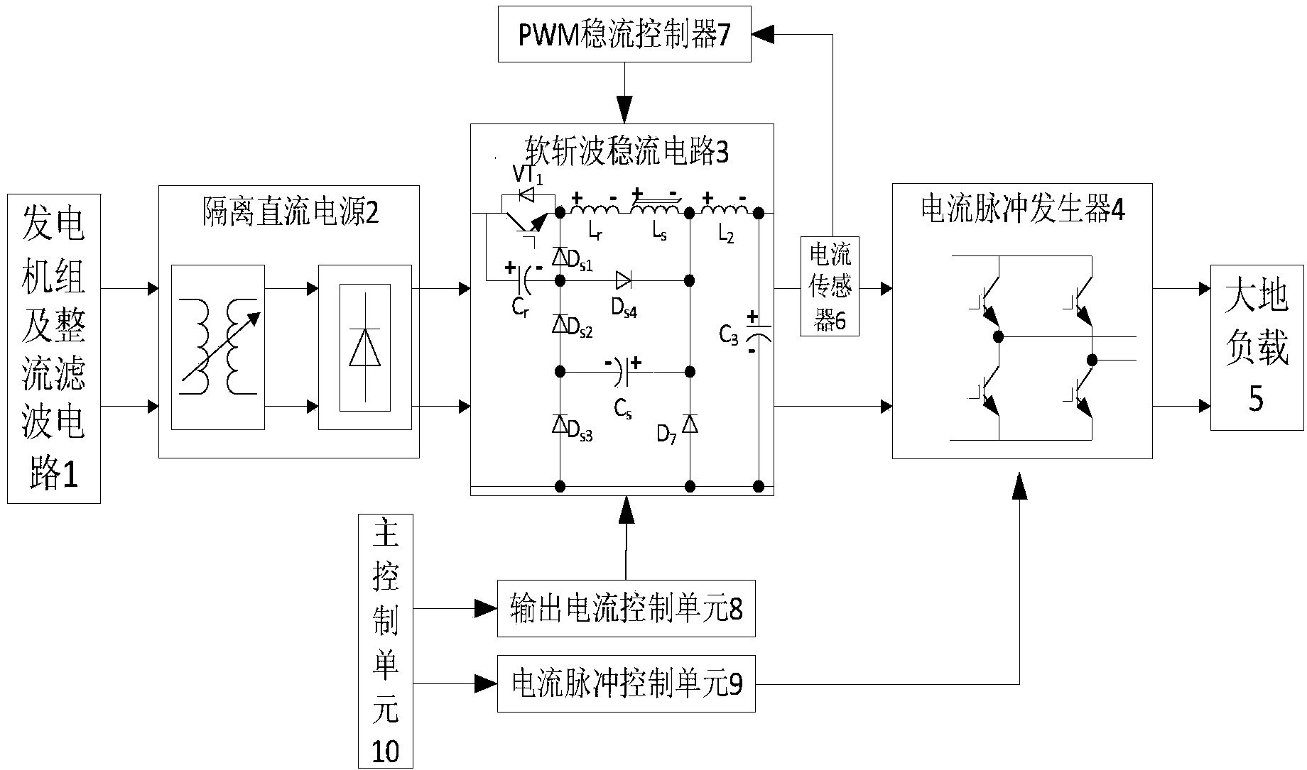
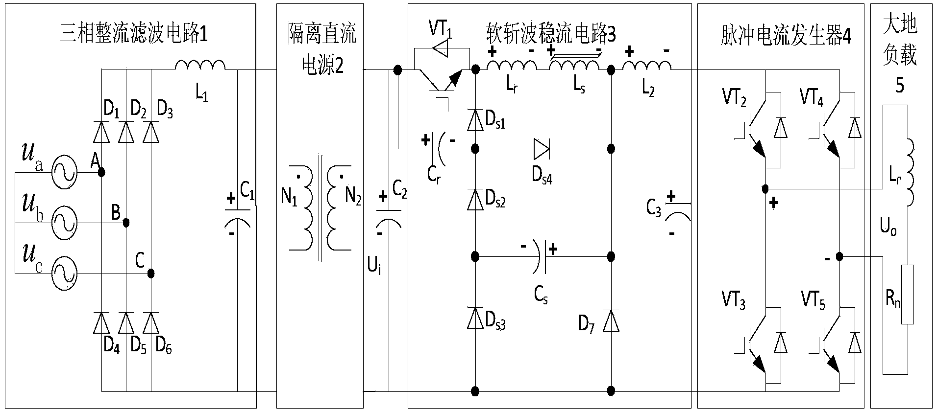
[0054] figure 1 It is a structural block diagram of an electric source emission device with soft chopping characteristics, which is connected by a generator set and a rectification filter circuit 1 through an isolated DC power supply 2 and a soft chopping current stabilization circuit 3, and the soft chopping current stabilization circuit 3 The positive pole is connected to the ground load 5 through the current sensor 6 and the current pulse generator 4, the negative pole output of the soft chopper current stabilization circuit 3 is connected to the ground load 5 through the current pulse generator 4, and the current sensor 6 is connected to the ground load 5 through the PWM steady current controller 7. The soft chopper current stabilization circuit 3 is connected, the main control unit 10 is connected with the soft chopper current stabilization circuit ...


PUM


Abstract

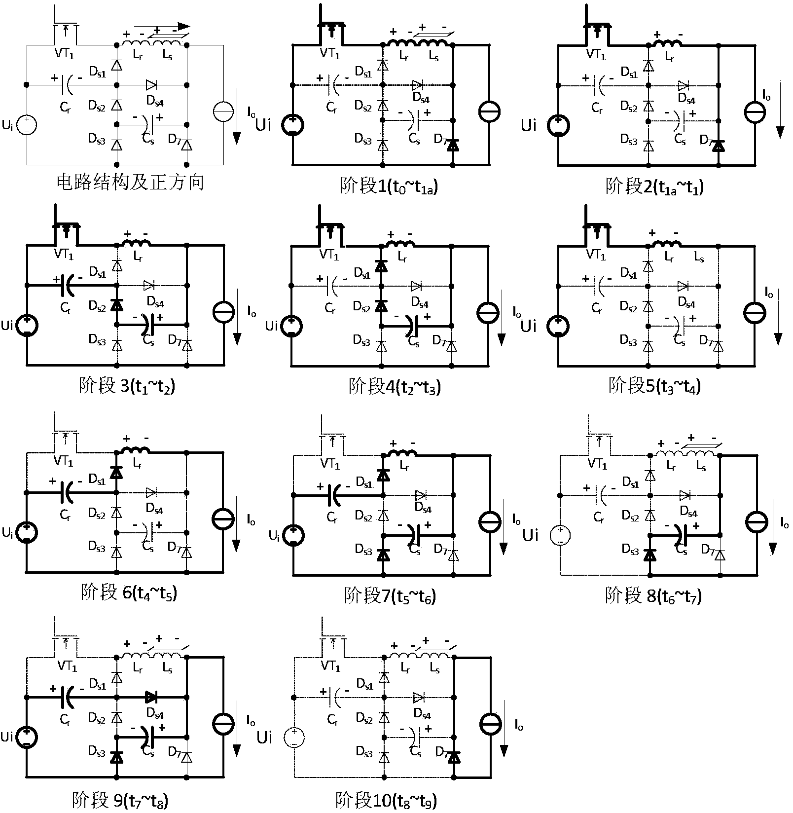
The invention relates to an electrical source emission device and control method with a soft chopping wave characteristic. The device is formed by connecting a three-phase alternative current generator set with a ground load through an isolated direct current power supply, a soft chopping wave steady flow circuit and a current pulse generator. A passive lossless soft switch structure is adopted in the soft chopping wave steady flow circuit, the passive lossless soft switch structure is composed of a main switching tube VT1, a main diode D7, buffer capacitance Cr, energy-storage capacitance Cs, a buffer inductance Lr, a saturation inductance Ls, diodes ranging from Ds1 to Ds4 and filter circuits L2 and C3, and the structure can achieve the soft opening up and soft shutting off of the main switching tube VT1of soft chopping wave steady flow circuit, and the soft shutting off of the main diode D7. Compared with an existing hard chopping wave steady flow electric source transmission device, the power density of the instrument is improved, application region of the device is expanded, electromagnetic interference is reduced, and the steady flow accuracy of the device is improved. The device is within normal operation range, no extra voltage stress is introduced to the main switching tube VT1, the mean free error time is increased, and the service life of the device is prolonged.

Description

technical field [0001] The invention relates to a geophysical prospecting electrical instrument with passive soft chopping characteristics, which is particularly suitable for transmitting pulse current amplitudes of tens of amperes and transmitting powers of n×10 0 kW to n×10 2 Between kW, the internal electromagnetic environment of the device is complex and the electrical source emission device with high steady current accuracy. Background technique [0002] Frequency-domain magnetotelluric detection relies on electrical source transmitters to emit pulse currents with variable frequency and waveform to the earth load, which can realize geophysical exploration such as metal ore detection, geothermal resource exploration, coal field and oil and gas structure detection. The main frequency domain magnetotelluric detection methods include Controlled Source Audio-frequency Magnetotelluric (CSAMT), complex resistivity method and frequency domain induced electricity method. [00...

Claims


Application Information

Patent Timeline
IPC IPC(8): H02M9/04H02M3/335
Inventor 周逢道李骄松薛开昶
Owner JILIN UNIV
Learn More