A Broadband Substrate Integrated Waveguide Filter Using U-Slot Lines

A technology of integrating waveguides and U-shaped grooves on a substrate, which is applied in the field of wireless communication, can solve the problems of difficult design and processing, large loss, complex structure, etc., and achieves the effects of simple production, overcoming large loss and small volume.

Inactive Publication Date: 2016-08-17
SOUTH CHINA UNIV OF TECH
View PDF5 Cites 0 Cited by
  • Summary
  • Abstract
  • Description
  • Claims
  • Application Information

AI Technical Summary

Problems solved by technology

[0006] 3) The above two broadband filters are designed on the microstrip line, and the relative bandwidth is very wide, but they have a common defect that the loss is relatively large
Simulation results such as Figure 3c As shown, the relative bandwidth is close to 65%, and the loss is small, but this structure is more complicated and not easy to design and process

Method used


Image

  • A Broadband Substrate Integrated Waveguide Filter Using U-Slot Lines
  • A Broadband Substrate Integrated Waveguide Filter Using U-Slot Lines
  • A Broadband Substrate Integrated Waveguide Filter Using U-Slot Lines

Examples


Embodiment 1

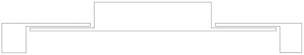
[0043] Such as Figure 4 As shown, the broadband substrate-integrated waveguide filter of this embodiment includes a substrate-integrated waveguide, and the substrate-integrated waveguide includes a dielectric substrate 1 and two layers of metal patches arranged on the front and back sides of the dielectric substrate 1 (the metal patch on the front side 2, the metal patch on the reverse side is not shown in the figure, the same as in Embodiments 2 to 4) and two rows of metal through holes, the two layers of metal patches constitute the upper and lower walls of the substrate integrated waveguide; the upper and lower rows The metal through-holes run through the metal patch 2 on the front of the dielectric substrate 1, the dielectric substrate 1, and the metal patch on the back of the dielectric substrate 1 in sequence. The two rows of metal through-holes are equivalent to electrical walls and constitute the left and right walls of the substrate integrated waveguide. The upper ro...

Embodiment 2

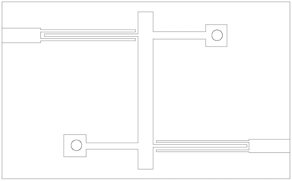
[0048] Such as Figure 7 As shown, the main features of the broadband substrate integrated waveguide filter in this embodiment are: improving on the basis of the filter structure in Embodiment 1, adding a U-shaped groove line, that is, the metal patch 2 on the front side of the dielectric substrate 1 Two U-shaped groove lines 7 are etched on the top, and the two U-shaped groove lines 7 form a groove line unit symmetrically up and down. The two sides of the U-shaped slot line 7 face downward (that is, an inverted U shape), and the two sides of the U-shaped slot line 7 located at the bottom face up. The substrate integrated waveguide of the slot line unit is etched to form a multimode resonator, and its cut-off The frequency is obtained by formula (1), and the transmission zero is obtained by the following formula (3):

[0049] f zero = c 2 ( 2 ...

Embodiment 3

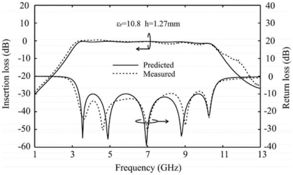
[0052] Such as Figure 10 As shown, the main features of this embodiment are: improving on the basis of the filter structure of Embodiment 2, and adding two metal through holes, that is, a second metal through hole is also provided between the groove line unit and the upper row of metal through holes 3 A metal through hole 8, a second metal through hole 9 is also provided between the groove line unit and the lower row of metal through holes 4, the first metal through hole 8 and the second metal through hole 9 are symmetrical up and down, and in turn The metal patch 2 on the front side of the dielectric substrate 1 , the dielectric substrate 1 , and the metal patch on the back side of the dielectric substrate 1 are penetrated. Such as Figure 11 As shown in the simulation results, both in-band return loss and out-of-band rejection have been improved to some extent.


PUM


Abstract

The invention discloses a broadband substrate integrated waveguide filter adopting a U-shaped groove line. The broadband substrate integrated waveguide filter comprises a substrate integration waveguide. The substrate integration waveguide comprises a dielectric substrate, two metal patches, an upper row of metal through holes and a lower row of through holes, wherein the two metal patches are arranged on the front surface and the rear surface of the dielectric substrate respectively and form an upper wall and a lower wall of the substrate integration waveguide, the upper row of metal through holes and the lower row of through holes form a left wall and a right wall of the substrate integration waveguide, and the U-shaped groove line is etched in the metal patch on the front surface of the dielectric substrate to enable the substrate integration waveguide to form a multimode resonator. According to the broadband substrate integrated waveguide filter, the substrate integration waveguide form the multimode resonator by means of the etched U-shaped groove line, complexity caused by etching a periodical EBG structure on the substrate integration waveguide is eliminated, requirements of a miniaturized broadband communication system can be met, the shortcoming of large loss of the traditional micro-strip broadband filter is overcome, the problem of high manufacturing cost caused by utilizing a metallic waveguide is solved, and therefore, the broadband substrate integrated waveguide filter adopting the U-shaped groove line has good application prospect.

Description

technical field [0001] The invention relates to a broadband substrate integrated waveguide filter, in particular to a broadband substrate integrated waveguide filter using U-shaped groove lines, which belongs to the field of wireless communication. Background technique [0002] Wireless communication technology is playing an increasingly important role in real social life. As an important component in the field of wireless communication, the demand for band-pass filters is also increasing. The earlier microstrip bandpass filter was widely used due to its convenience in plan drawing and board making, but this kind of filter has a large loss, especially at high frequencies, it will produce a lot of energy radiation. With the continuous development of communication technology, the requirements for filters are getting higher and higher. Although the millimeter-wave filter using metal waveguide can achieve better technical indicators, it is expensive and cannot be widely used; t...

Claims


Application Information

Patent Timeline
Patent Type & Authority Patents(China)
IPC IPC(8): H01P1/20
Inventor 王世伟陈瑞森汪凯郭在成林景裕褚庆昕
Owner SOUTH CHINA UNIV OF TECH
Why Eureka
Try Eureka