Permanent magnet synchronous motor and rotor thereof
A permanent magnet synchronous motor and rotor technology, which is applied to synchronous machine parts, synchronous motors with static armatures and rotating magnets, and magnetic circuit rotating parts, etc. Increase, performance degradation and other problems, to achieve the effect of reducing torque fluctuation level, reducing cogging torque, and simple rotor structure
- Summary
- Abstract
- Description
- Claims
- Application Information
AI Technical Summary
Problems solved by technology
Method used
Image
Examples
Embodiment 1
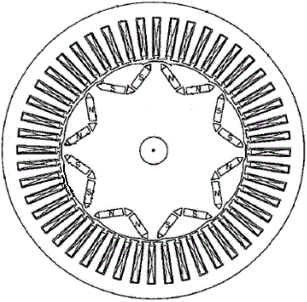
[0066] permanent magnet synchronous motor, the rotor of which is Figure 4 As shown, including core 1;
[0067] The iron core 1 is cylindrical, and p S pole magnetic steel sheets 11 and p N pole magnetic steel sheets 11 are evenly arranged inside the iron core around the axis, and p is a positive integer; the S pole magnetic steel sheets are the same as the N pole magnetic steel sheets. The steel sheets are arranged at intervals;
[0068] The iron core 1 is provided with two d-axis surface grooves 14 on the surface of the rotor iron core at each magnetic steel sheet;
[0069] Two d-axis surface grooves 14 corresponding to a magnetic steel sheet are symmetrically distributed on both sides of the magnetic steel sheet center line (i.e. the d-axis);
[0070] Corresponding to the axial spacing W of two d-axis surface grooves 14 of a magnetic steel sheet, approximately equal to the tooth end width W of the stator teeth of the permanent magnet synchronous motor (such as being 90 of...
Embodiment 2
[0076] Based on the permanent magnet synchronous motor of Embodiment 1, the permanent magnet synchronous motor is a fractional slot motor, such as Figure 5 As shown, the iron core 1 is provided with q-axis surface grooves 12 in the axial direction on the outer surface located in the middle of the adjacent S-pole magnetic steel sheets and N-pole magnetic steel sheets (ie at the q-axis of the rotor).
[0077] The average torque of the permanent magnet synchronous motor T=p[φ f i d +(L d -L q )i d i q ], where p is the number of motor pole pairs, φ f is the flux linkage generated by the fundamental magnetic field of the permanent magnet in the stator winding, id is the d-axis current of the stator, iq is the q-axis current of the stator, Ld is the d-axis inductance of the stator winding, and Lq is the q-axis inductance of the stator winding. The torque T of the permanent magnet synchronous motor is mainly composed of two parts, that is, the synchronous torque generated by ...
Embodiment 3
[0083] Based on the permanent magnet synchronous motor of embodiment two, such as Image 6 As shown, the iron core 1 is also provided with an internal hole 13 along the axial direction in the middle of the adjacent S-pole magnetic steel sheets and the N-pole magnetic steel sheets (ie at the q-axis of the rotor).
[0084] Opening holes at the q-axis of the iron core can reduce the torque fluctuation caused by the salient pole effect of the motor on the one hand, and can effectively curb the magnetic flux leakage between the poles and improve the utilization rate of the magnet steel of the motor; on the other hand, the q-axis of the iron core After the hole is opened inside, the reluctance of the q-axis magnetic circuit increases, and the d-axis weak magnetic reverse field entering the magnetic steel part becomes lower under the same stator current condition, which enhances the anti-demagnetization performance of the magnetic steel.
[0085] In the permanent magnet synchronous m...
PUM
 Abstract
Description
Claims
Application Information
 - R&D
- Intellectual Property
- Life Sciences
- Materials
- Tech Scout
- Unparalleled Data Quality
- Higher Quality Content
- 60% Fewer Hallucinations
Browse by: Latest US Patents, China's latest patents, Technical Efficacy Thesaurus, Application Domain, Technology Topic, Popular Technical Reports.
© 2025 PatSnap. All rights reserved.Legal|Privacy policy|Modern Slavery Act Transparency Statement|Sitemap|About US| Contact US: help@patsnap.com


