Power supply control device for power amplifier tube and power-on and power-off control method thereof

A power amplifier tube, power supply control technology, applied in power amplifiers, high-frequency amplifiers, electronic switches, etc., can solve the problems of difficult to cover the temperature drift curve of the power amplifier tube, difficult to meet the power-on and power-off control of the power amplifier tube, and difficult temperature compensation.

Active Publication Date: 2014-07-30
COMBA TELECOM SYST CHINA LTD
View PDF4 Cites 18 Cited by
  • Summary
  • Abstract
  • Description
  • Claims
  • Application Information

AI Technical Summary

Problems solved by technology

GaN is the representative of the third-generation semiconductor. Because of its wide band gap, the microwave power amplifier made of GaN material is referred to as GaN power amplifier tube. It has the advantages of high operating frequency, high efficiency and wide bandwidth. The gate voltage and drain There are strict requirements on the switching sequence of the voltage. If there is a problem with the power supply, it will easily cause damage to the power amplifier tube.
[0005] It can be seen that for the power amplifier tube of the third-generation semiconducto

Method used


Image

  • Power supply control device for power amplifier tube and power-on and power-off control method thereof
  • Power supply control device for power amplifier tube and power-on and power-off control method thereof
  • Power supply control device for power amplifier tube and power-on and power-off control method thereof

Examples


Embodiment Construction

[0030] The specific implementation of the power supply control device for the power amplifier tube of the present invention will be described in detail below in conjunction with the accompanying drawings.

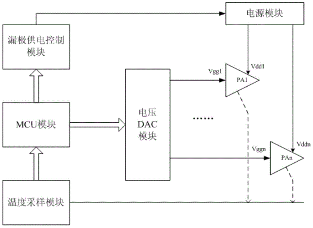
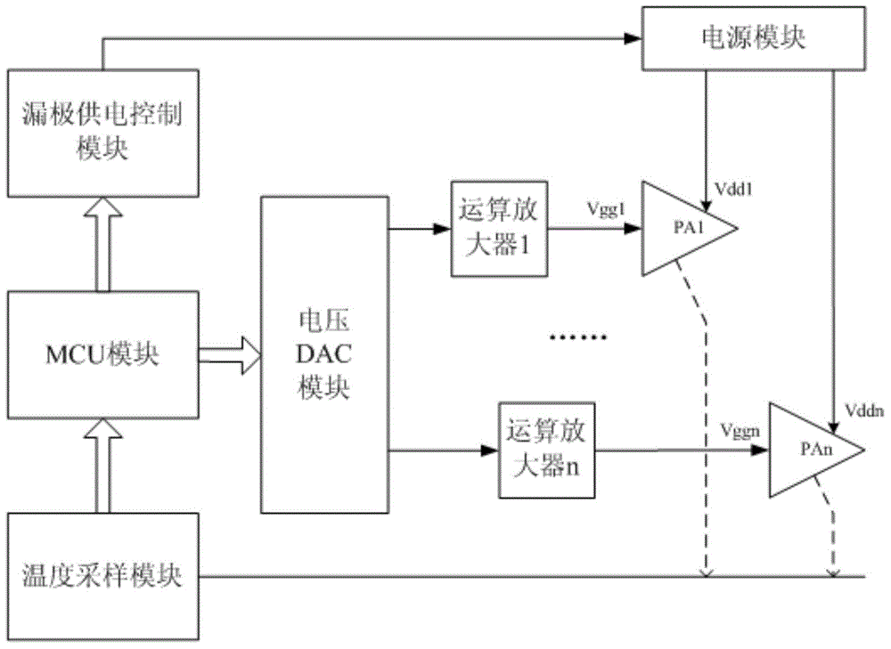
[0031] refer to figure 1 as shown, figure 1 It is a schematic structural diagram of the power supply control device of the power amplifier tube of the present invention, including: MCU (Micro Control Unit, micro control unit) module, temperature sampling module, voltage DAC (Digital to analog converter, digital to analog converter) module, power supply module, A drain power supply control module; wherein, the MCU module is connected to the grid of the power amplifier tube through the voltage DAC module, connected to the drain of the power amplifier tube through the drain power supply control module, and connected to the power amplifier tube through the temperature sampling module;

[0032] The temperature sampling module is used to collect the working temperature of the po...


PUM


Abstract

The invention relates to a power supply control device for a power amplifier tube and a power-on and power-off control method thereof. The device comprises an MCU (Microprogrammed Control Unit) module, a temperature sampling module, a voltage DAC (Digital to Analog Converter) module, a power supply module and a drain electrode power supply control module; the MCU module is user for controlling the drain electrode power supply of the power amplifier tube and the negative voltage power supply of a grid in a unified mode, and the grid voltage can be conveniently, quickly and dynamically adjusted through the control of the negative voltage power supply of the grid, so that self-adapted dynamic adjustment under different working temperatures is realized, and correctness and reliability for power-on and power-off sequence of the power amplifier tube are ensured through the combination of the control of the grid power supply, thus the power amplifier tube can be better protected from being burnt by incorrect power-on and power-off timing sequence, the power-on and power-off control timing sequence of the power amplifier tube is met, the power amplifier tube is always at a good working condition, and the reliability of power amplification system is promoted. According to the power supply control device for the power amplifier tube, the correctness and reliability for power-on and power-off sequence of the power amplifier tube are ensured, and the reliability of the whole power amplification system is directly promoted.

Description

technical field [0001] The invention relates to the technical field of mobile communication power amplifiers, in particular to a power supply control device for a power amplifier tube and a power-on and power-off control method thereof. Background technique [0002] The static operating point of the RF power amplifier tube has temperature characteristics, and changes in its static operating current will affect the system's gain, efficiency, and linearity. Therefore, keeping the static operating point of the power amplifier tube constant during work is one of the key points in the design of the power amplifier module. To maintain a constant static operating point of the power amplifier tube requires real-time compensation of the gate voltage according to the working state of the power amplifier module. [0003] At present, the power amplifiers commonly used in the radio frequency field are mainly LDMOS (Lateral double-diffused metal-oxide semiconductor, laterally diffused me...

Claims


Application Information

Patent Timeline
IPC IPC(8): H03F3/20H03F3/189H03K17/08
Inventor 凌兴锋龙润坚刘江涛黄建安
Owner COMBA TELECOM SYST CHINA LTD
Why Eureka
Try Eureka