
High-temperature blowing and deashing technology for deduster

A dust collector and ash cleaning technology, applied in chemical instruments and methods, dispersed particle separation, dispersed particle filtration, etc., can solve the problems of increased equipment cost, difficulty in adapting to medium gas, complex structure, etc., and achieve stable gas temperature and long-term. The effect of effective dust removal and filtration

Inactive Publication Date: 2014-08-06
HENAN DRAGON INTO COAL TECH CO LTD
View PDF5 Cites 4 Cited by
  • Summary
  • Abstract
  • Description
  • Claims
  • Application Information

AI Technical Summary

Problems solved by technology

Among them, after the coal material is decomposed and burned, a large amount of dust-containing gas to be finely processed is produced. In the current dry dust removal process, it is most common to use a dust bag as a fine dust collector. However, the normal working temperature that the dust bag can withstand is usually lower The temperature of dust-removing gas is much lower and it is difficult to transform. In addition, the filter tube structure is used to filter the high-temperature dust-containing gas to realize gas-solid separation and gas purification. The filtered and purified dust-containing gas enters the clean gas chamber, and the dust is filtered and retained. In the dust removal room of the dust collector, it is deposited into the ash hopper, and the outer surface of the filter element used in the dust collector will absorb a large amount of particle dust during the process of filtering and dust removal. As the dust continues to increase, it will affect the filtration quality. To remove the accumulated dust, some manufacturers design to use mechanical dust removal devices, such as installing brushes at the front of the manipulator, or mechanical oscillation methods, but not only the structure is complicated, but also the filter element of the dust collector is easy to be damaged due to poor action consistency. After the filter element is damaged, the dust enters the dust collector The clean gas chamber of the device will bring the polluted and purified gas into the subsequent process, causing great losses
Nowadays, the blowing pipe is commonly used to achieve reverse dust cleaning, but the result of back blowing will inevitably make the gas outside the dust collector enter the dust collector again, especially the space before purification, and the external gas flow rate is large and the temperature drop is large, which is easy to cause Temperature changes, the temperature around the filter element in the dust collector is too low, it is easy to cause coal tar components to condense and damage the filter element; if the backflush temperature is too high, the performance of the backflush valve and other equipment will be higher, and the equipment cost will increase.
At present, the operating temperature of the commonly used dust collectors generally does not exceed 280°C, and is mainly used for bag dust removal, and many backflush temperatures use normal temperature or low temperature gas sources, which are difficult to adapt to the medium gas containing strict temperature requirements described in the present invention. Therefore, there is an urgent need to make further improvements and innovations in filter element injection and dust removal.

Method used


Image

  • High-temperature blowing and deashing technology for deduster
  • High-temperature blowing and deashing technology for deduster
  • High-temperature blowing and deashing technology for deduster

Examples


Embodiment 1

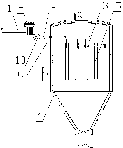
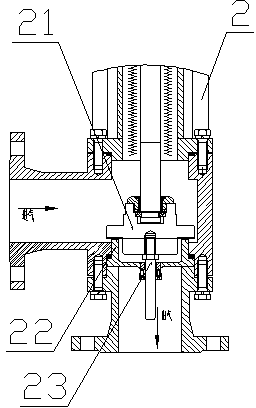
[0024] Such as figure 1 , figure 2 As shown, a high-temperature blowing soot cleaning process for a dust collector involves equipment including a blowing gas delivery pipe 1, a blowing valve 2, and a nozzle 3. The blowing gas delivery pipe 1 communicates with a high-temperature pressurized gas. During the forward filtration process of the filter element 5 of 4, the blowing valve 2 is periodically started to carry out back-blowing and dust-cleaning. A high-pressure expansion zone is formed to quickly remove the accumulated dust attached to the outside of the filter element 5. After the backflushing and dust removal process is completed, the injection valve 2 is closed to resume the forward filtering process of the filter element 5.

[0025] Wherein, the high-temperature pressurized gas source is connected to an external gas supply device, and the gas supply device is an inert gas, such as nitrogen, and a booster device 10 is arranged on the injection gas delivery pipe 1; Th...

Embodiment 2

[0028] A high-temperature blowing soot cleaning process for a dust collector, the difference from Embodiment 1 is that it involves equipment, and the high-temperature pressurized gas source is connected to the air outlet pipe of the clean air chamber of the dust collector 4 .

Embodiment 3

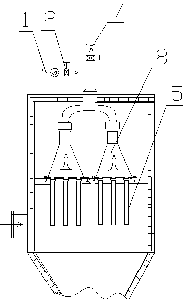
[0030] A high-temperature jet cleaning process for dust collectors, the difference from Embodiment 1 is: as image 3 As shown, which involves in the equipment, the outlet end of the blowing gas delivery pipe 1 is connected to the venturi tube 8 through the blowing valve 2, the venturi tube 8 covers the upper part of the filter element 5, and the upper part of the venturi tube 8 is set There are branch gas paths, which are connected to the blowing gas delivery pipe 1 and the purified gas outlet 7 respectively.


PUM


Abstract

The invention discloses a high-temperature blowing and deashing technology for a deduster, and relates to equipment comprising a blowing gas conveying pipe, a blowing valve and blowing nozzles. The high-temperature blowing and deashing technology for the deduster is characterized in that the blowing gas conveying pipe is communicated with a high-temperature supercharging gas; the blowing valve is started up periodically for back blowing and deashing in the normal flow filtration process of a filter element of the deduster; in the back blowing and deashing process, the gas blowing temperature is controlled to be above 290 DEG C; the blowing gas forms a high-pressure expansion region in a filter element; deposited ash attached to the outer part of the filter element is removed rapidly; the blowing valve is shut off after the back blowing and deashing process is finished, and the normal flow filtration process of the filter element is recovered. The high-temperature blowing and deashing technology for the deduster, which is provided by the invention, breaks through the traditional low-temperature back blowing and deashing technology, filters high-temperature gases, especially the high-temperature gas of high tar and high-dust gas effectively, moreover, enables the operation temperature of the deduster to be improved by one level, improves the dedusting efficiency and energy utilization ratio, and has favorable popularization and using values.

Description

technical field [0001] The invention belongs to the technical field of jet dedusting equipment, and in particular relates to a high-temperature jet dedusting process for dust collectors. Background technique [0002] At present, my country is short of oil and natural gas resources, and coal will remain the most important primary energy source for a long time to come. However, there are many problems and challenges in the process of coal conversion and utilization, such as low comprehensive utilization efficiency, serious environmental pollution, shortage of water resources, and large carbon dioxide emissions. Therefore, it is an inevitable choice for the development of my country's energy industry to develop coal efficient and clean comprehensive utilization technology to achieve energy conservation and emission reduction. The "Twelfth Five-Year Plan" for the development of clean coal technology and technology, which is encouraged by the state, includes industrial policies ...

Claims


Application Information

Patent Timeline
Patent Type & Authority Applications(China)
IPC IPC(8): B01D46/00B01D46/42
Inventor 朱书成赵家亮李金峰庞志峰
Owner HENAN DRAGON INTO COAL TECH CO LTD
Learn More