
Method and device for deep oil removal of wastewater containing low-concentration sump oil

A low-concentration, waste water technology, applied in the direction of grease/oily substance/suspton removal device, separation method, mining wastewater treatment, etc., can solve the problem of not meeting the requirements of deep degreasing of waste water

Active Publication Date: 2014-08-06
EAST CHINA UNIV OF SCI & TECH
View PDF10 Cites 44 Cited by
  • Summary
  • Abstract
  • Description
  • Claims
  • Application Information

AI Technical Summary

Problems solved by technology

However, this equipment is mainly used for the pretreatment of oily sewage, and it cannot meet the requirements of deep degreasing of wastewater.

Method used

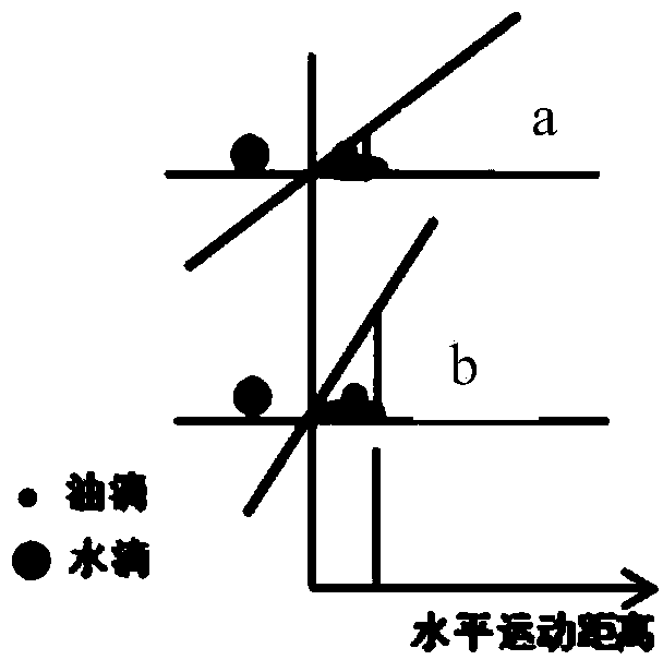
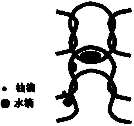
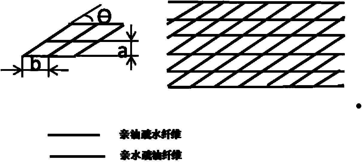

Image

  • Method and device for deep oil removal of wastewater containing low-concentration sump oil
  • Method and device for deep oil removal of wastewater containing low-concentration sump oil
  • Method and device for deep oil removal of wastewater containing low-concentration sump oil

Examples


Embodiment 1

[0040] On the offshore oil platform of an oil company’s crude oil exploitation, the method and device of the present invention suitable for deep degreasing wastewater containing low-concentration sewage oil are used to degrease the production wastewater after sedimentation, swirling, and air flotation separation , the deoiled sewage reaches the discharge standard and is discharged into the sea.

[0041] The schematic diagram of the above-mentioned device is shown in Figure 6 As shown, it includes shell 1, oily wastewater inlet 2, fluid rectifier 3, X-shaped braided layer 4 (fiber coalescing and separation layer), corrugated reinforced separation layer 5, Ω-shaped braided layer 10 (fiber coalescing and replenishing layer), Oil bag 6, oil phase outlet 7 and purified water phase outlet 9. The oily waste water inlet 2 is at one end of the upper part of the housing 1 , the oil bag 6 is at the other end of the upper part of the housing 1 , the oil bag 6 has a liquid level gauge 8 , ...

Embodiment 2

[0051] A petrochemical company's oil refinery sewage treatment workshop sewage adopts a kind of equipment suitable for deep degreasing of waste water containing low concentration sewage oil according to the present invention, and degreases the waste water after sedimentation pretreatment, and achieves biochemical treatment after degreasing Require.

[0052] Other conditions are the same as embodiment 1, and the specific operation process and effect of different parts are described as follows:

[0053] The operating conditions of the wastewater after gravity sedimentation pretreatment in the sewage treatment workshop: operating pressure: 0.2MPa; operating temperature 40-60°C, sewage oil content 80-100mg / L.

[0054] Requirement index: The oil content in the sewage after degreasing is not more than 25mg / L.

[0055] Solution selection: In this solution, the sewage has undergone simple sedimentation and separation at the initial stage, so most of the oil droplets in the wastewater...


PUM

PropertyMeasurementUnit
particle diameteraaaaaaaaaa
angleaaaaaaaaaa

Abstract

The invention relates to a method and device for deep oil removal of wastewater containing low-concentration sump oil. The method comprises the following steps: allowing the wastewater containing the low-concentration sump oil to enter the device through an inlet, firstly uniformly distributing a fluid by use of a flow regulator, secondly capturing trace of oil droplets through a knitted layer formed by an oleophylic and hydrophobic fiber knitted layer and a hydrophilic and oleophobic knitted layer which are knitted in a certain manner, demulsifying and separating trace of agglomerated and grown oil-in-water emulsion, and finally realizing rapid agglomeration, growing and separation in a corrugation enhancement and settling separation manner. The invention also provides a set of device for implementing the method. The device comprises a plurality of parts including a shell, a feeding pipe, the flow regulator, a fiber agglomerated layer, a corrugation enhanced separating layer, a liquid level meter and the like. The technique is high in separation efficiency, small in energy consumption, long in continuous running period and widely applicable to a treatment process of each wastewater containing the low-concentration sump oil.

Description

technical field [0001] The invention belongs to the oil-water separation technology in the field of environmental protection, and in particular relates to a method and a device for deep oil removal of waste water containing low-concentration dirty oil. Background technique [0002] With the increasingly stringent environmental protection, the requirements for deep degreasing of oily wastewater are getting higher and higher. For example, my country has increased the oil content index of offshore oil mining sewage from the previous 20mg / L to 10mg / L; the oil content index of sewage treatment plants has entered biochemical treatment is also improving. [0003] The difficulty of oily wastewater treatment varies with its source and the state and composition of oil pollution. The treatment methods can be divided into physical methods (sedimentation, mechanical, centrifugation, coarse granulation, filtration, membrane separation, etc.) according to the principle; physical chemical m...

Claims


Application Information

Patent Timeline
Patent Type & Authority Applications(China)
IPC IPC(8): C02F1/40
CPCC02F1/006C02F1/288C02F1/40C02F2101/32C02F2103/10C02F2103/365
Inventor 杨强许萧卢浩王朝阳杨森
Owner EAST CHINA UNIV OF SCI & TECH
Learn More