Evaporation source heating device

A heating device and evaporation source technology, which is applied in vacuum evaporation coating, sputtering coating, gaseous chemical coating, etc., can solve the problems of cracking and unstable evaporation rate, and achieve uniform heating, good thermal conductivity, Guarantee the effect of evaporation effect

Active Publication Date: 2016-04-20
TCL CHINA STAR OPTOELECTRONICS TECH CO LTD
View PDF6 Cites 0 Cited by
  • Summary
  • Abstract
  • Description
  • Claims
  • Application Information

AI Technical Summary

Problems solved by technology

[0006] The difference between the evaporation temperature of the organic material and its cracking temperature is very small. The temperature difference inside the crucible of the point-type evaporation source is often large (upper heat and lower cooling). The rate cannot be stabilized; increase the temperature to make the material thermally stable, and often the above material has the risk of cracking

Method used


Image

  • Evaporation source heating device
  • Evaporation source heating device
  • Evaporation source heating device

Examples


Embodiment Construction

[0026] In order to further illustrate the technical means adopted by the present invention and its effects, the following describes in detail in conjunction with preferred embodiments of the present invention and accompanying drawings.

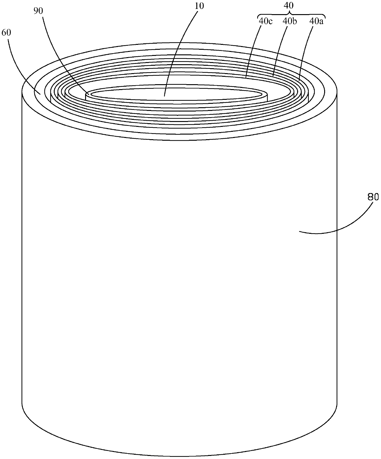
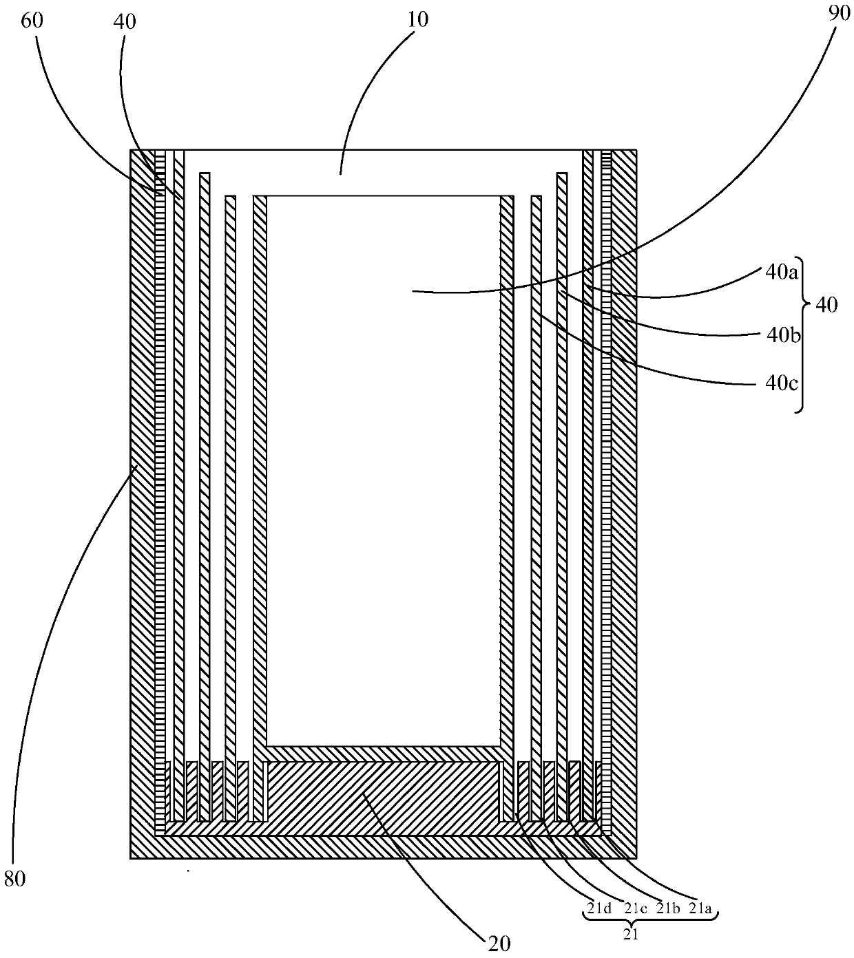
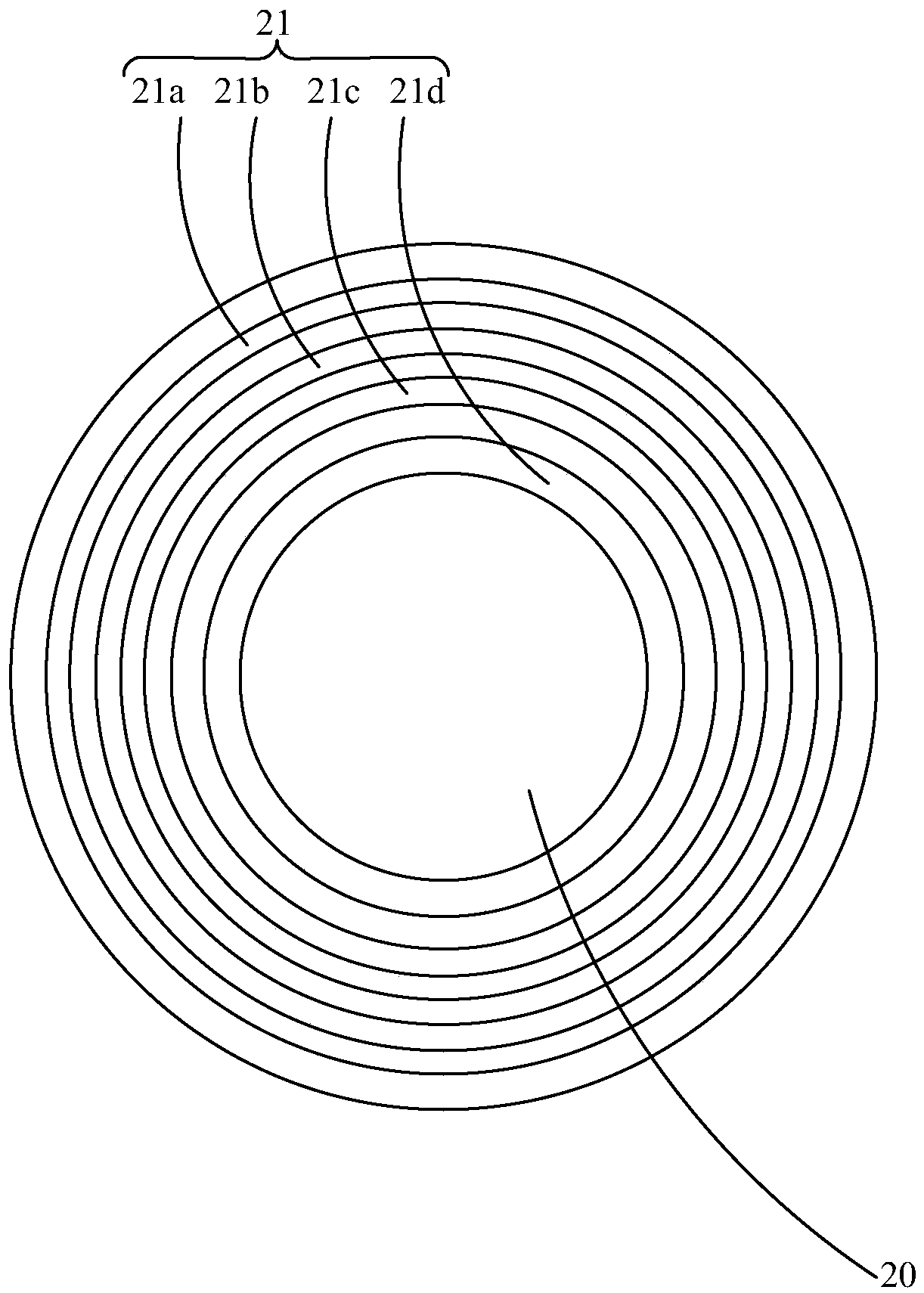
[0027] see Figure 1-4 , the present invention provides an evaporation source heating device 10, comprising a base 20, a housing 80 connected to the base 20, a heating element 60 disposed inside the housing 80, a digital device disposed inside the heating element 60 and mounted on the base 20. A metal cylinder 40, and a crucible 90 set in the metal cylinder 40. The base 20 is accommodated in the housing 80, the base 20 is provided with several concentric annular grooves 21, the metal cylinder 40 is a cylinder, and the several metal cylinders 40 are respectively installed in the several grooves 21 superior. The heating element 60 is a heating resistance wire.

[0028] In this embodiment, the base 20 has four concentric annular grooves 21, wh...


PUM

PropertyMeasurementUnit
thicknessaaaaaaaaaa

Abstract

The invention provides an evaporation source heating device, comprising: a base, an outer casing connected to the base, a heating element arranged inside the outer casing, several metal cylinders arranged inside the heating element and installed on the base, and a plurality of metal cylinders arranged on the metal cylinder inside the crucible. In the evaporation source heating device of the present invention, several metal cylinders are arranged between the heating element and the crucible, and the several metal cylinders are installed on the base. When heating, the heat of the heating element is gradually conducted through the several metal cylinders. The heat is conducted to the crucible. Due to the good thermal conductivity of the metal cylinder, the heat distribution on it is uniform, so that the crucible is heated evenly and the evaporation effect is guaranteed.

Description

technical field [0001] The invention relates to the field of manufacturing organic electroluminescent devices, in particular to an evaporation source heating device. Background technique [0002] Organic electroluminescent device is a kind of self-luminous device, which has the advantages of low voltage, wide viewing angle, fast response speed and good temperature adaptability. ), a new generation of flat panel display technology after liquid crystal (LCD). [0003] From the perspective of the molecular weight of the organic electroluminescent materials used, organic electroluminescent devices are divided into small molecule organic electroluminescent devices (OLED) and polymer electroluminescent devices (PLED). Due to the difference in molecular weight, the two organic electroluminescent devices The manufacturing process of luminescent devices is also very different. OLEDs are mainly prepared by thermal evaporation, and PLEDs are prepared by spin coating or inkjet printing...

Claims


Application Information

Patent Timeline
Patent Type & Authority Patents(China)
IPC IPC(8): C23C14/26
CPCC23C14/26C23C14/12C23C14/243C23C16/0209C23C16/448
Inventor 邹清华
Owner TCL CHINA STAR OPTOELECTRONICS TECH CO LTD
Why Eureka
Try Eureka