Immersed tube drainage structure and method for handling suddenly-produced foundation pit water bursting and fountains through immersed tube drainage structure

A sudden, immersed tube technology, applied in immersed tube precipitation treatment of sudden foundation pit water surge, immersed tube precipitation structure, fountain field, can solve the problems of low porosity, scrapped wells, large amount of engineering, etc. Simple and effective in reducing construction costs

Inactive Publication Date: 2014-08-06
JIANGSU NANTONG SANJIAN CONSTRUCTION GROUP CO LTD
View PDF6 Cites 15 Cited by
  • Summary
  • Abstract
  • Description
  • Claims
  • Application Information

AI Technical Summary

Problems solved by technology

[0004] These water filter pipes have a common defect that the porosity is low, the higher the porosity, the better the water inlet effect
In addition, the cast iron wire-wrapped water filter pipe and the cement water filter pipe have low strength and are easy to break. They are prone to breakage during the pumping process of water wells in unstable formations, resulting in adverse consequences for the wells to be scrapped.
[0005] A disclosed patent name is a prefabricated concrete pipe immersed tube dewatering structure and dewatering method for foundation pits, patent number 201210102995.

Method used


Image

  • Immersed tube drainage structure and method for handling suddenly-produced foundation pit water bursting and fountains through immersed tube drainage structure

Examples


Embodiment Construction

[0019] The following examples are only used to illustrate the present invention, but not to limit the protection scope of the present invention.

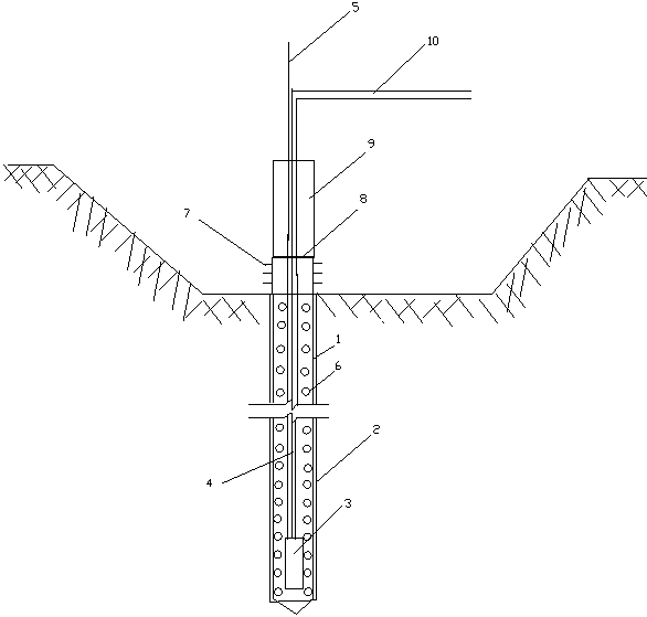
[0020] Such as figure 1 As shown, an immersed tube dewatering structure of the present invention includes a steel pipe 1, a submersible pump 3, a water pipe 4 and a drain pipe 10, and the water suction hole 6 is drilled on the steel pipe 1 wall, and the water suction hole 6 is drilled by a drilling tool , the operation on the ground is quite convenient. In addition, the water absorption hole 6 has two functions. On the one hand, it can make water enter quickly from the water absorption hole 6 instead of only relying on a steel pipe mouth; on the other hand, the water absorption hole 6 is wrapped with nylon tight Mesh 2, make water can enter, and the silt that is greater than the aperture of nylon dense mesh can not enter, and silt is just deposited at the bottom of the pit.

[0021] The steel pipe 1 is located on the upper surface ...


PUM

PropertyMeasurementUnit
Apertureaaaaaaaaaa

Abstract

The invention discloses an immersed tube drainage structure, and further discloses a method for handling suddenly-produced foundation pit water bursting and fountains through the immersed tube drainage structure. When the water bursting phenomenon obviously occurs in a foundation pit and mud is sprayed out, landfill is conducted through original soil within the range of a core tube which has been dug, and then well digging and water pumping are conducted. A plurality of wells are formed for the core tube, and shaft bottom elevations are reduced till the shaft bottom elevations are below the natural ground and extend into high-water-content layers; after formation, a submerged pump is placed in each well to conduct water pumping; the upper openings of the wells are connected to form a water pumping network so that underground water can be pumped to a drainage system on the upper edge of the foundation pit; digging is continued after water inside the well is lowered below the foundation bottom elevations of the core tube; in the digging process, water pumping systems of the water pumps keeps working, blinding concrete pouring is conducted instantly after earth excavation conducted on the portions is completed; after pouring, the water pumping systems of the water pumps in the wells stop working after the raft foundation concrete pouring is completed and the strength reaches 75% of the designed strength. The drainage construction method is simple in process, and construction cost of foundation pit drainage construction can be effectively reduced.

Description

technical field [0001] The invention relates to an immersed tube dewatering structure. [0002] The invention relates to a method for treating sudden foundation pit water surge and fountain by sinking tube dewatering. Background technique [0003] Foundation pit dewatering mainly includes sump dewatering method and well point dewatering method. Among them, well point dewatering method has the characteristics of large displacement, deep precipitation, and is not limited by soil quality. It is suitable for rich groundwater, deep foundation pit, and foundation pit. Underground dewatering for projects with large ground area; the well point dewatering method is to construct a certain number of dewatering wells around the foundation pit before excavation of the foundation pit, weld the water filter pipe at the lower part of the dewatering well, and use pumping equipment to pump out the groundwater in the well, so that The method of keeping the excavated soil dry at all times; ...

Claims


Application Information

Patent Timeline
IPC IPC(8): E02D19/10
Inventor 陈辉瞿学忠姜雪岐黄裕平
Owner JIANGSU NANTONG SANJIAN CONSTRUCTION GROUP CO LTD
Why Eureka
Try Eureka