

Split pupil laser differential confocal Raman spectrum test method and device
A spectrum test and differential confocal technology, which is applied in the directions of measuring devices, spectrometry/spectrophotometry/monochromator, Raman scattering, etc., can solve the problem of strict requirements on out-of-focus position and the inability to achieve absolute displacement measurement, Limit the focus tracking accuracy and application range of the confocal Raman system, and achieve the effect of simplifying the optical path structure
Active Publication Date: 2014-08-06
BEIJING INSTITUTE OF TECHNOLOGYGY
View PDF4 Cites 29 Cited by
- Summary
- Abstract
- Description
- Claims
- Application Information
AI Technical Summary
Problems solved by technology
However, the existing confocal microscopic measurement system has the following disadvantages: when the confocal intensity response hypotenuse is used for measurement, absolute displacement measurement cannot be achieved, and the measurement accuracy is limited by the nonlinearity of the confocal intensity response curve hypotenuse measurement interval, the intensity of the light source Factors such as fluctuations, scattering and reflection characteristics of the measured surface; when using focus tracking measurement, because the focus of the confocal microscopic measurement system corresponds to the apex with the worst confocal intensity response sensitivity, which restricts the further improvement of the focus tracking accuracy of this type of confocal sensor , which in turn limits the focus tracking accuracy and application range of traditional confocal Raman systems
However, because the differential confocal Raman spectroscopy test method uses a dual-path physical pinhole structure, the structure of the differential confocal measurement system is relatively complex, and the requirements for the defocus position are strict, and the installation and adjustment are difficult, which increases the error source: In addition, due to the limitation of the principle of the differential confocal microscope system, it is usually difficult to balance the resolving power, working distance and field of view
Method used
View moreImage
Smart ImageViewing Examples

Examples
Embodiment
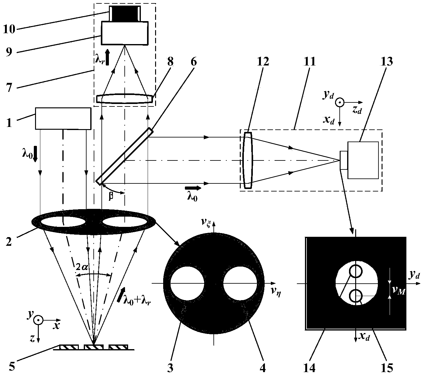
[0073] In this embodiment, the dichroic spectroscopic system 6 is a Notch filter, the spectrum detector 9 is a Raman spectrum detector, the image acquisition system 13 is a CCD, and the image magnification system 28 is a magnifying objective lens.
Login to View More PUM
 Abstract
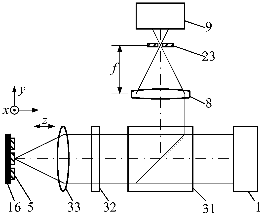
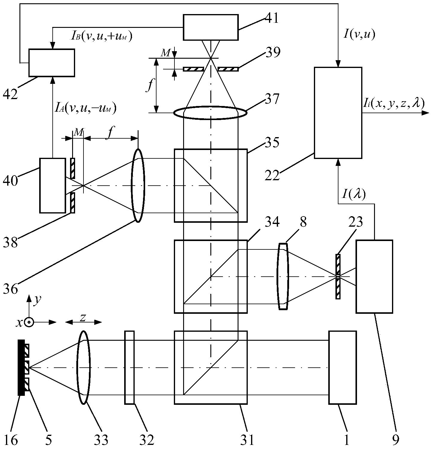
The invention belongs to the technical field of microscopicspectral imaging detection, and relates to a split pupil laser differential confocal Raman spectrum test method and device. According to the test method and device, a split pupil laser differential confocal microtechnique and a laser Raman spectrum detection technique are organically combined, precise imaging of three-dimensional geometrical positions is realized through segmentation focal spot differential detection, the optical path structure of a traditional differential confocal microscopic system is simplified, advantages of an original laser differential confocal system and a split pupil confocal system are inherited, and multi-mode switching and processing of split pupil laser differential confocal microscopic detection, laser confocal Raman spectrum detection and laser differential confocal Raman spectrum detection can be realized only through softwareswitching processing. The test method and device provide a new technological approach for detection ofnanoscale microcell three-dimensional geometrical positions and spectrum, can be applied to fields of biomedicine, industrial precision detection and the like, and has the broad application prospect.
Description
technical field [0001] The invention belongs to the technical field of micro-spectral imaging, combines differential confocal microscopic technology and spectral detection technology, and relates to a high-spatial-resolution spectral imaging and detection method and device of "map-spectrum integration", which can be used for microscopic imaging of various samples. High spatial resolution imaging and detection of Raman spectroscopy in the region. technical background [0002] In 1990, G.J.Puppels and other scholars first invented the confocal Raman spectroscopy microscopy technique when observing the morphology and composition of single cells and chromosomes and successfully used it in experiments. Laser confocal Raman spectroscopy technology causes molecules (or lattices) to vibrate through incident laser light and loses (or gains) part of the energy, causing the frequency of scattered light to change. By analyzing the scattered light, the composition, structure and Relativ...
Claims
Login to View More Application Information
Patent Timeline
 Patent Type & AuthorityApplications(China)
IPC IPC(8): G01N21/65G01J3/44
CPCG01J3/44G01N21/65G02B21/0032G02B21/0076
Inventor赵维谦盛忠邱丽荣邵荣君
OwnerBEIJING INSTITUTE OF TECHNOLOGYGY