Device and method for measuring magnetostriction coefficient through linear frequency modulation multi-beam laser heterodyne second harmonic method

A technology of magnetostriction coefficient and linear frequency modulation, applied in the field of optical measurement, can solve the problem of low measurement accuracy of ferromagnetic material length variation

Inactive Publication Date: 2014-08-06
HEILONGJIANG UNIV
View PDF4 Cites 0 Cited by
  • Summary
  • Abstract
  • Description
  • Claims
  • Application Information

AI Technical Summary

Problems solved by technology

[0005] The purpose of the present invention is to solve the problem of low measurement accuracy of the length variation of ferromagnetic materials in the process of measuring the magnetostriction coef

Method used


Image

  • Device and method for measuring magnetostriction coefficient through linear frequency modulation multi-beam laser heterodyne second harmonic method
  • Device and method for measuring magnetostriction coefficient through linear frequency modulation multi-beam laser heterodyne second harmonic method
  • Device and method for measuring magnetostriction coefficient through linear frequency modulation multi-beam laser heterodyne second harmonic method

Examples


specific Embodiment approach 1

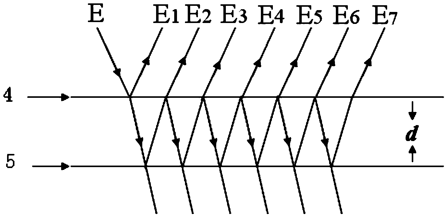
[0057] Specific implementation mode one: the following combination figure 1 Describe the present embodiment, the device for measuring the magnetostriction coefficient by the chirp multi-beam laser heterodyne second harmonic method described in the present embodiment, it includes the ferromagnetic material sample 1 to be measured, and it also includes the chirp laser 2, the first plane mirror 3, thin glass plate 4, second plane mirror 5, converging lens 6, photodetector 7, signal processing system 8, two fixed rods 9 and excitation coil 10,

[0058] The two ends of the ferromagnetic material sample 1 to be tested are respectively bonded with a fixed rod 9, the free end of one fixed rod 9 is fixed by a fixing piece, and the free end of the other fixed rod 9 is bonded and fixed to the back of the second plane reflector 5 ; The ferromagnetic material sample 1 to be tested is placed in the center of the excitation coil 10; the excitation coil 10 is powered by a DC stabilized power ...

specific Embodiment approach 2

[0061] Specific implementation mode two: the following combination figure 1 Illustrate this embodiment, this embodiment will further illustrate embodiment one, the signal processing system 8 described in this embodiment is made up of filter 8-1, preamplifier 8-2, analog-to-digital converter 8-3 and digital signal processor 8-4 composition,

[0062] The filter 8-1 is used to receive the photocurrent signal output by the photodetector 8, the filter 8-1 outputs the filtered signal to the preamplifier 8-2, and the analog signal amplified by the preamplifier 8-2 is sent to the analog-to-digital conversion 8-3, the analog signal is converted into a digital signal by the analog-to-digital converter 8-3 and then sent to the digital signal processor 8-4.

[0063] Filter 8-1 is a low pass filter.

specific Embodiment approach 3

[0064] Embodiment 3: This embodiment further describes Embodiment 1 or 2. The initial distance between the thin glass plate 4 and the second flat mirror 5 in this embodiment is 30 mm.


PUM

PropertyMeasurementUnit
Thicknessaaaaaaaaaa

Abstract

The invention provides a device and method for measuring a magnetostriction coefficient through the linear frequency modulation multi-beam laser heterodyne second harmonic method and belongs to the technical field of optical measurement. The device and method aim to solve the problem that in the process of measurement of the magnetostriction coefficient of ferromagnetic materials, the precision of measurement of the variation of the lengths of the ferromagnetic materials is low. The device comprises a ferromagnetic material sample to be measured, a linear frequency modulation laser device, a first plane mirror, a thin glass plate, a second plane mirror, a convergent lens, a photoelectric detector, a signal processing system, two fixed rods and an exciting coil. The method comprises the steps that the photoelectric detector is made to start to receive light beam signals, a digital signal processor continuously collects light current signals output by the photoelectric detector and processes collected difference frequency signals, the current distance between the thin glass plate and the second plane mirror is obtained according to the relationship between the frequency and the distance, and then the magnetostriction coefficient of the ferromagnetic material sample to be measured is obtained according to the formula of the magnetostriction coefficient. The device and method for measuring the magnetostriction coefficient through the linear frequency modulation multi-beam laser heterodyne second harmonic method are suitable for magnetostriction coefficient measurement.

Description

technical field [0001] The invention relates to a device and a method for measuring a magnetostriction coefficient by a linear frequency modulation multi-beam laser heterodyne second harmonic method, and belongs to the technical field of optical measurement. Background technique [0002] The phenomenon that the magnetic domains of ferromagnets are oriented and arranged under the action of an external magnetic field, which causes the lattice spacing in the medium to change, and the length of the ferromagnet to change, is called the magnetostrictive effect. Since this phenomenon was first discovered by Joule in 1842, it is also called the Joule effect. Magnetostriction not only has an important influence on the magnetism of the material, especially on the initial magnetic permeability, coercive force, etc., but also its effect itself is widely used in practice, such as: magnetostriction technology can It is used in mechanical vibration and ultrasonic transducers, and also has...

Claims


Application Information

Patent Timeline
IPC IPC(8): G01R33/18
Inventor 李彦超甄佳奇杨九如冉玲苓高扬杨瑞海杜军丁群王春晖马立峰于伟波
Owner HEILONGJIANG UNIV
Why Eureka
Try Eureka