
A deep hole drilling machine

A deep hole drilling machine and drilling tool technology, which is applied in the direction of boring/drilling, drilling/drilling equipment, and drilling templates for workpieces, etc., which can solve the problem of low radial precision of hole processing and large feed inertia of workpieces , Unable to correct problems such as deflection, to achieve the effect of improving machining accuracy, prolonging life, and improving temperature rise

Active Publication Date: 2018-01-16
郭昆兰
View PDF7 Cites 0 Cited by
  • Summary
  • Abstract
  • Description
  • Claims
  • Application Information

AI Technical Summary

Problems solved by technology

However, high-pressure oil is still required for cooling. Because the center line of the applied feed force, the axial force of drilling, the center of gravity of the guide rail, and the friction force of the guide rail do not coincide, torque is easily generated, causing the axis of the machining hole to deviate, and the workpiece does not rotate, which cannot be corrected. Deviation, the radial accuracy of hole machining is not high, the productivity is low, and the feed inertia of large workpieces is large, which makes the tool vulnerable

Method used


Image

  • A deep hole drilling machine
  • A deep hole drilling machine
  • A deep hole drilling machine

Examples


Embodiment Construction

[0017] The present invention will be described in detail below in conjunction with the accompanying drawings.

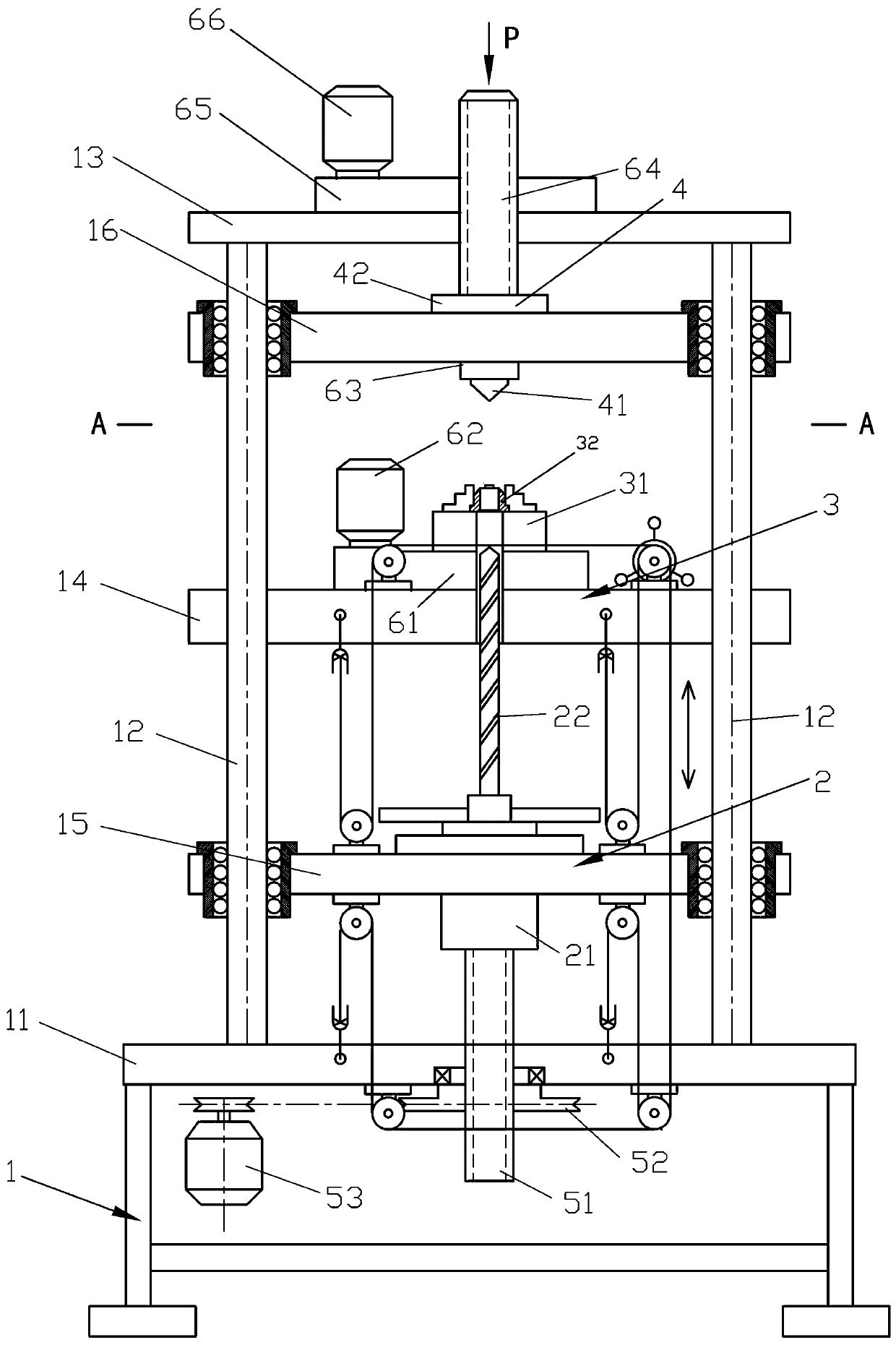
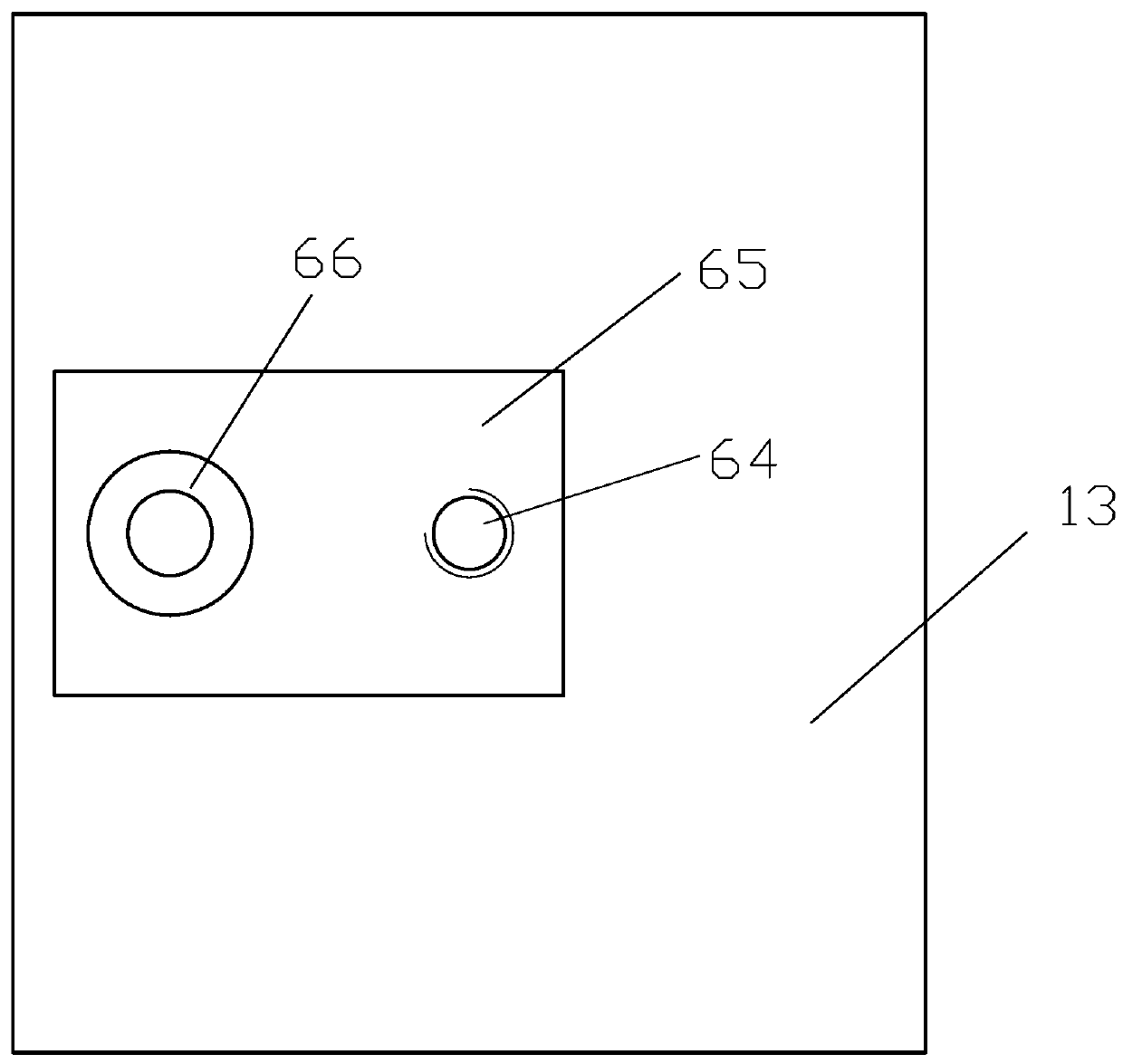
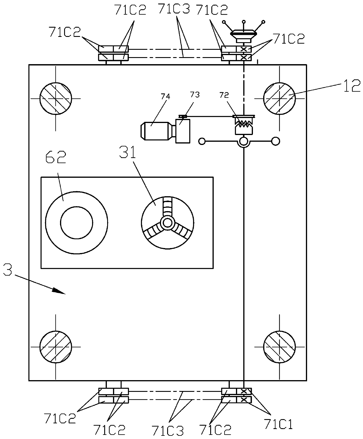
[0018] Such as Figure 1-3 As shown, a deep hole drilling rig comprises a derrick type fuselage 1, an inverted drilling tool assembly 2, a clamp assembly 3, a mandrel assembly 4, a transmission mechanism, and the fuselage 1 includes a guide rail 12, a fixed lower platform 11, a fixed The upper platform 13, the fixed workpiece platform 14, the drilling tool connection platform 15, the ejector rod connection platform 16, the inverted drilling tool assembly 2 is composed of the spindle seat 21 and the cutting tool 22, and the guide rail 12 of the fuselage 1 is also the supporting column. The tool connection platform 15 and the ejector rod connection platform 16 are planar bearing sliding platforms that move up and down along the guide rail 12. The fixture assembly 3 is composed of a workpiece fixture 31 and a drilling mold 32. The ejector rod assembly 4 is composed of a...


PUM


Abstract

The invention relates to a deep hole drilling machine, comprising a machine body, an inverted drill, a clamp, an ejection rod and a transmission mechanism, wherein the machine body is provided with guide rails, a drill connecting platform, an ejection rod connecting platform, a fixed upper platform, a fixed lower platform and a workpiece platform; the drill connecting platform and the ejection rod connecting platform move up and down along the guide rails; the workpiece platform is located between the drill connecting platform and the ejection rod connecting platform; the transmission mechanism is provided with a spindle transmission mechanism, a clamp transmission mechanism, an ejection rod transmission mechanism and a feeding transmission mechanism. By applying the structure that an inverted drill bit not only rotates, but also feeds, and a workpiece rotates only relative to the drill, the rotation speed of the drill bit is decreased under the condition of the same processing efficiency; the centrifugal force of cuttings is lowered, so that the friction force against a hole wall is lowered; the cuttings are discharged in an accelerating way at a speed close to the speed of a freely falling body; the heat radiation of the drill bit is obviously bettered; with the reduction of abrasion, the service life is prolonged; as the drill and the workpiece simultaneously make relative rotation, the cutting position is changed from fixation to peripheral rotation; the axis deviation and the vibration are eliminated; due to the positive / negative traction and the synchronous up-and-down displacement of a feeding mechanism, the perpendicularity of the drill in feeding is guaranteed without swing.

Description

technical field [0001] The invention belongs to machining equipment for drilling, in particular to a deep hole drilling machine. Background technique [0002] Drilling of holes is a common processing procedure in mechanical processing. The corresponding equipment includes desktop drilling rigs and vertical drilling rigs. The depth of the processed holes is basically about 5 times the diameter of the hole, but sometimes it needs to be processed. The hole depth / aperture is more than 5-30 times, which is commonly known as deep hole processing. The processing of this type of hole basically adopts the method of graded drilling. When drilling to a certain depth, the drilling tool needs to be replaced. At the position, the greater the swing of the drill bit, the more the hole is drilled, the more difficult it is to discharge the iron filings, the wear and friction of the workpiece, iron filings, and the drill bit are getting more and more serious, and the heat generated is not easy...

Claims


Application Information

Patent Timeline
Patent Type & Authority Patents(China)
IPC IPC(8): B23B41/02B23B47/06B23B47/20
CPCB23B41/02B23B47/28B23Q1/017B23Q5/10B23Q5/32B23Q11/0042
Inventor 郭昆兰
Owner 郭昆兰
Learn More