Pneumatic gripper mechanical arm

A manipulator and air gripper technology, which is applied in the field of plastic processing machinery, can solve the problems of small number of manipulators, increase the size of the machine and occupy space, and achieve the effects of compact structure, convenient maintenance and replacement, and high efficiency.

Inactive Publication Date: 2014-08-13
台州迈格机械模具有限公司
View PDF6 Cites 8 Cited by
  • Summary
  • Abstract
  • Description
  • Claims
  • Application Information

AI Technical Summary

Problems solved by technology

In the existing manipulator, its two clamping arms are respectively installed on the driving device. During the action, the two clamping arms rotate around their respective rotation axes respectively. When the clamping arms are opened, the distance in the horizontal direction is relatively large. The distance between the manipulators is required to be large, and the number of manipulators that can be installed in a limited space is small, which increases the volume and floor space of the machine itself to a certain extent; in addition, the movement process of the manipulators needs to be as smooth as possible , small friction to reduce energy loss and improve efficiency

Method used


Image

  • Pneumatic gripper mechanical arm
  • Pneumatic gripper mechanical arm
  • Pneumatic gripper mechanical arm

Examples


Embodiment 1

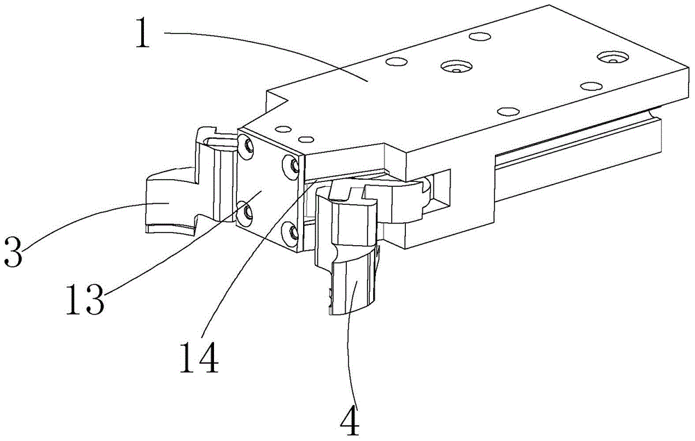
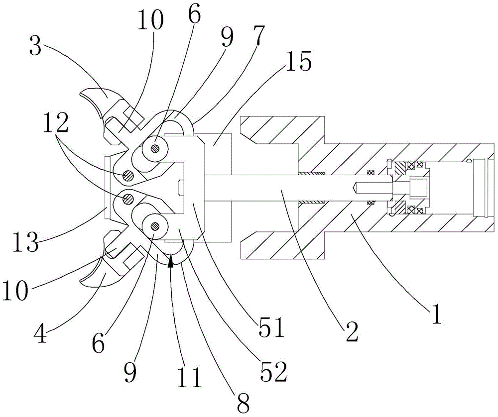
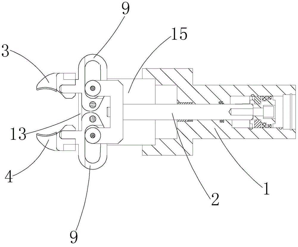
[0024] like Figure 1-5 As shown, the air claw manipulator includes a cylinder body 1, a piston, a cylinder rod 2, and a pair of clamping arms connected to the cylinder rod 2 that can be relatively gathered and opened, which are called the left clamping arm 3 and the right clamping arm 4 herein. One end of the cylinder rod 2 is connected with the piston, and the other end is connected with the clamp arm. One end of the cylinder rod 2 connected with the clamp arm is provided with a U-shaped frame 5. The U-shaped frame 5 has a transverse arm 51 in a horizontal direction and two vertical arms. The vertical arm 52 and the cross arm 51 are connected to the cylinder rod 2, and the ends of the two vertical arms 52 are respectively provided with a bearing 6, and the left and right clamping arms 3 and 4 respectively pass through a bracket, which are referred to as the left bracket 7 and the right bracket here. 8. Slidably connected to the two vertical arms 52. Both the left and right b...

Embodiment 2

[0027] The difference between this embodiment and embodiment 1 is:

[0028] like Figure 6-9 As shown, the left bracket 7 and the right bracket 8 are rotatably connected to the cylinder block 1 through a common support pin 12. The second connecting part 10 is provided with a bearing groove 11 on the first connecting part 9, and the acute angle β between the long axis direction of the first connecting part 9 and the long axis direction of the second connecting part 10 is 50-80°. In this embodiment The middle is about 65°. The left support 7 and the right support 8 are rotatably connected to the cylinder block 1 through a common support pin 12, which makes the structure of the manipulator more compact, and at the same time, reduces the machining accuracy of the manipulator, making the process more convenient and accurate.

[0029] The air claw manipulator of the invention has the advantages of compact structure, small volume, low energy consumption, good effect and wide applic...


PUM


Abstract

The invention discloses a pneumatic gripper mechanical arm and belongs to the technical field of plastics machining machinery. The pneumatic gripper mechanical arm comprises an air cylinder body, a piston, an air cylinder rod, and a pair of clamping arms which are connected to the air cylinder rod and can be oppositely folded and unfolded. The pneumatic gripper mechanical arm is characterized in that one end of the air cylinder rod, which is connected with the clamping arms, is provided with a U-shaped frame, the cross arm of the U-shaped frame is connected with the air cylinder rod, and the end portions of the two longitudinal arms of the U-shaped frame are respectively provided with a bearing; the pair of clamping arms are slidingly connected to the two vertical arms of the U-shaped frame through a support with a bearing groove, the bearings work inside the bearing groove, and the support is rotatably connected to the air cylinder body through a support pin. The pneumatic gripper mechanical arm has the advantages of being simple and compact in structure, small in size, low in energy consumption and the like.

Description

technical field [0001] The invention relates to a manipulator, in particular to an air claw manipulator, which is used for clamping and conveying plastic pipe blanks, and belongs to the technical field of plastic processing machinery. Background technique [0002] All kinds of plastic bottles such as mineral water bottles, cosmetic bottles, medicine bottles, etc. are widely used in daily life, medicine, chemical industry and other fields. Plastic bottle blowing machine is the most common machine for producing plastic bottles in the market, mainly including frame, heating device, spacing device, conveying device, bottle blowing device and other components. After the steps, enter the mold for blow molding. In the conveying process of each link, it is often necessary to clamp and convey the preform by the preform clamping manipulator. During the working process, the clamping manipulator needs to perform a series of opening and closing actions. In the existing manipulator, it...

Claims


Application Information

Patent Timeline
Patent Type & Authority Applications(China)
IPC IPC(8): B25J15/08B29C49/42
Inventor 蔡佳翰
Owner 台州迈格机械模具有限公司
Why Eureka
Try Eureka