A new type of submersible thruster impeller

A submersible flow propeller and impeller technology, applied in water/sewage treatment, chemical instruments and methods, biological water/sewage treatment, etc., can solve the problems of large impeller diameter, increased unbalance, connection failure, etc., and achieve guaranteed strength and stiffness, improving stress conditions, and improving service life

Active Publication Date: 2015-09-30
LANSHEN GRP CORP LTD
View PDF6 Cites 0 Cited by
  • Summary
  • Abstract
  • Description
  • Claims
  • Application Information

AI Technical Summary

Problems solved by technology

[0004] 2. The two blades are symmetrically installed on the hub. Due to manufacturing errors and uneven distribution of blade mass, after the blades are installed, the unbalance of the impeller far exceeds the theoretical value, which has a great impact on the quality of the submersible flowmaker.
[0005] 3. Even if the manufacturing quality of the blade and hub meets the design requirements, the unbalance of the impeller will exceed the theoretical value due to improper quality control of the installation
[0006] 4. Due to the large diameter of the impeller, the axial force and radial force are also large. After a period of operation, the connection of related fasteners and keys will fail to a certain extent. Due to the large diameter of the impeller and the blade is a space surface, It will also produce a certain amount of unbalance, which will affect the service life of the flowmaker
[0007] 5. Since the blade and the hub are manufactured separately, the overall weight is relatively large, the unbalance is also relatively large, and the installation is also difficult
[0008] 6. Due to the large diameter of the impeller, a certain deformation will also occur during use, increasing the unbalance

Method used


Image

  • A new type of submersible thruster impeller
  • A new type of submersible thruster impeller

Examples


Embodiment Construction

[0025] The following description is merely exemplary in nature and not intended to limit the disclosure, application or use. It should be understood that throughout the drawings, corresponding reference numerals indicate like or corresponding parts and features.

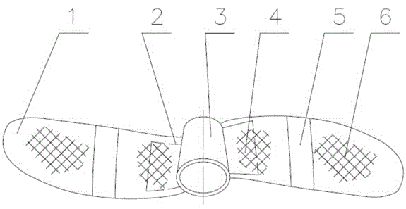
[0026] Such as figure 2 As shown, a novel submersible thruster impeller of the present invention includes a blade 1, a keel 2, a hub 3, an expansion resin 4, a rib 5, and a high-performance foam 6. The impeller is an integral impeller with two blades, and its appearance is made of reinforced glass fiber reinforced plastic material that wraps the hub 3 and the keel 2. Each impeller includes a hub 3 and two blades 1, the keel 2 is welded on the hub 3, and the rib 4 passes through The mold is fixed on the easily deformable position of the blade 1 to increase the rigidity, and the upper and lower parts of the blade 1 (the two blades are divided into two parts that are exactly the same and opposite in direction through ...


PUM

PropertyMeasurementUnit
diameteraaaaaaaaaa

Abstract

The invention discloses a novel submersible water impeller rotor. The submersible water impeller rotor is in an integrated form, and comprises a blade, a keel, a hub, expansible resin, a reinforcing rib and high-performance foam. The submersible water impeller rotor is characterized in that the keel is welded on the hub through a special tooling; a mold comprising the hub and keel components is folded into a whole after glass reinforced plastic containing the reinforcing rib is pasted by manual placement inside a split mold; reinforced expansion liquid resin and high-performance foam are sprayed into gaps at different parts, and are fully filled into the blade after being cured. The overall rotor disclosed by the invention has the advantages of being light in weight, small in amount of unbalance, stable in hydraulic performance and the like, has enough strength and rigidity and has certain flexibility.

Description

technical field [0001] The invention belongs to the technical field of environmental protection and relates to a novel impeller of a submersible thruster. Background technique [0002] The submersible flowmaker is widely used in low-speed push flow in sewage treatment plants, and is an ideal choice for water circulation mixing equipment in sewage treatment plants such as nitrification, denitrification and phosphorus removal. Such as figure 1 As shown, the existing submersible flow booster is mainly composed of impeller, mechanical seal seat, speed reducer, bearing seat, motor and sliding sleeve parts. The sliding sleeve parts are installed on the tail of the motor casing through fasteners, the reducer and the bearing seat are respectively connected with the casing of the motor with fasteners, the mechanical seal seat is installed on the reducer through fasteners, and the impeller is assembled on the reducer The end of the output shaft is fixed with a lock nut, and a certai...

Claims


Application Information

Patent Timeline
Patent Type & Authority Patents(China)
IPC IPC(8): C02F3/00C02F3/12C02F1/00B01F15/00
CPCY02W10/15Y02W10/10
Inventor 陈斌李善庭张荣年余必升许荣军林华兵谢东
Owner LANSHEN GRP CORP LTD
Why Eureka
Try Eureka