
Solid lubricated thrust sliding bearing capable of being continuously filled

A technology for thrust sliding bearings and solid lubrication, which is applied in the direction of sliding contact bearings, rotating bearings, bearings, etc., can solve the problems of insufficient fillability of solid lubricants for bearings, restrictions on the types of solid lubricants, and restrictions on load-carrying capacity, etc., to achieve Improvement of sustainable fillability, increase in types of use, and long bearing life

Inactive Publication Date: 2014-08-13
HEFEI UNIV OF TECH
View PDF4 Cites 2 Cited by
  • Summary
  • Abstract
  • Description
  • Claims
  • Application Information

AI Technical Summary

Problems solved by technology

One way is to impregnate the solid lubricant in the porous sintered metal or reinforced fiber fabric, so that it can be used as a surface covering to bond a solid lubricating film. In order to improve its load resistance, a backing can also be added. Bearings made by this method are limited by the properties of the lubricant material itself, so its load-carrying capacity is limited; another method is to drill holes or slots in various parts of the substrate, and pre-embed solid lubricants in it, so as to The solid lubricating film is formed on the surface of the substrate, and the solid lubricating film is filled mainly by the thermal expansion of the mosaic itself. Although the bearing made by this method improves the load-carrying capacity, the filling capacity of the bearing solid lubricant is insufficient, and it also limits the solid lubricant. Type of Lubricant

Method used


Image

  • Solid lubricated thrust sliding bearing capable of being continuously filled
  • Solid lubricated thrust sliding bearing capable of being continuously filled

Examples


Embodiment Construction

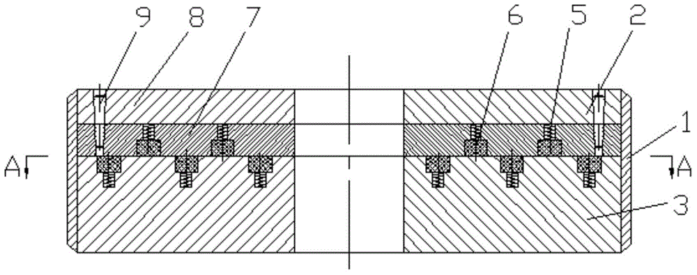
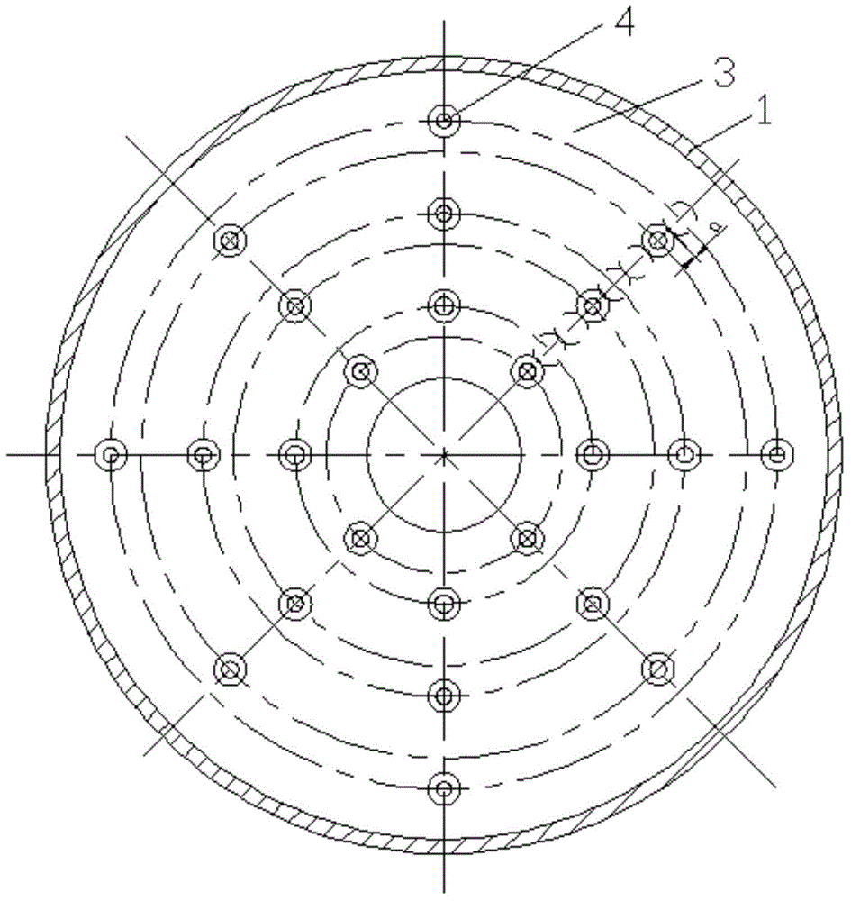
[0016] Refer to the attached drawings, a continuously filled solid lubrication thrust sliding bearing, including a sealing ring 1, a copper alloy upper ring 2, a steel lower ring 3, a lower ring 3 and a lower ring are installed on the lower part of the inner wall of the sealing ring 1 3 The upper ring 2 is installed on it. The upper ring 2 is composed of a base layer 8 distributed on the upper layer and a wear-resistant layer 7 on the lower layer. The base layer 8 and the wear-resistant layer 7 are connected by pins 9 and the wear-resistant layer of the upper ring Step holes 4 are arranged in the upper plane of the inner and lower ring 3 respectively. The small diameter section of the step hole 4 is equipped with a spring 5, and the large diameter section is equipped with a solid lubricating block 6. 6 are in contact with each other, and the stepped holes 4 on the contact planes of the upper and lower rings 2, 3 overlap in the relative sliding direction of the upper ring and the...


PUM


Abstract

The invention discloses a solid lubricated thrust sliding bearing capable of being continuously filled. The bearing comprises a seal ring, an upper ring and a lower ring, wherein the lower ring is arranged at the lower part of the inner wall of the seal ring; the upper ring is arranged above the lower ring; the upper ring comprises an upper base layer and a lower wear resistant layer which are connected with each other through pins; step holes are formed in the wear resistant layer of the upper ring and in the upper plane of the lower ring; a spring is arranged in the small diameter of each step hole; a solid lubricating block is arranged in the large diameter of each step hole; one end of each spring is in contact with the bottom of each step hole; the other end of each spring is in contact with the solid lubricating block; the step holes in the contact planes of the upper and lower rings are upwards arranged in a overlapping manner along the relative sliding direction of the upper ring and the lower ring, so that transferring films generated by the solid lubricating blocks in the step holes during friction cover the whole friction surface. The solid lubricated thrust sliding bearing capable of being continuously filled has the advantage of being high temperature resistant, high load resistant, good in self-lubricating and wear resistant under non-oil lubricating situation and has no thermal expansion requirement on a solid lubricant.

Description

Technical field [0001] The invention relates to a solid lubricant bearing, in particular to a thrust sliding bearing continuously filled with solid lubricant. Background technique [0002] At present, solid lubricating bearings have been widely used in various occasions, especially suitable for oil-free, high temperature, high load, low speed, anti-fouling, anti-corrosion, anti-radiation, and infiltration in water or vacuum solutions, and no lubricant can be added. Use under special working conditions. Solid lubrication bearings mainly rely on the formation of a solid lubrication film between two relatively moving friction pairs to reduce the friction between the friction pairs, protect the friction pairs, and improve the life of the bearing. The solid lubricating film has excellent load-bearing capacity, but its durability is not good, while the disadvantage of self-lubricating composite materials is poor load-bearing capacity. Therefore, in order to meet the requirements of a...

Claims


Application Information

Patent Timeline
IPC IPC(8): F16C17/04F16C33/10
Inventor 王伟刘勇刘焜刘小君
Owner HEFEI UNIV OF TECH
Learn More