
Directional constant velocity ball cage universal joint

A constant velocity spherical cage and universal joint technology, which is applied in the direction of elastic couplings, mechanical equipment, couplings, etc.

Active Publication Date: 2014-08-13
丛滨江 +1
View PDF5 Cites 2 Cited by
  • Summary
  • Abstract
  • Description
  • Claims
  • Application Information

AI Technical Summary

Problems solved by technology

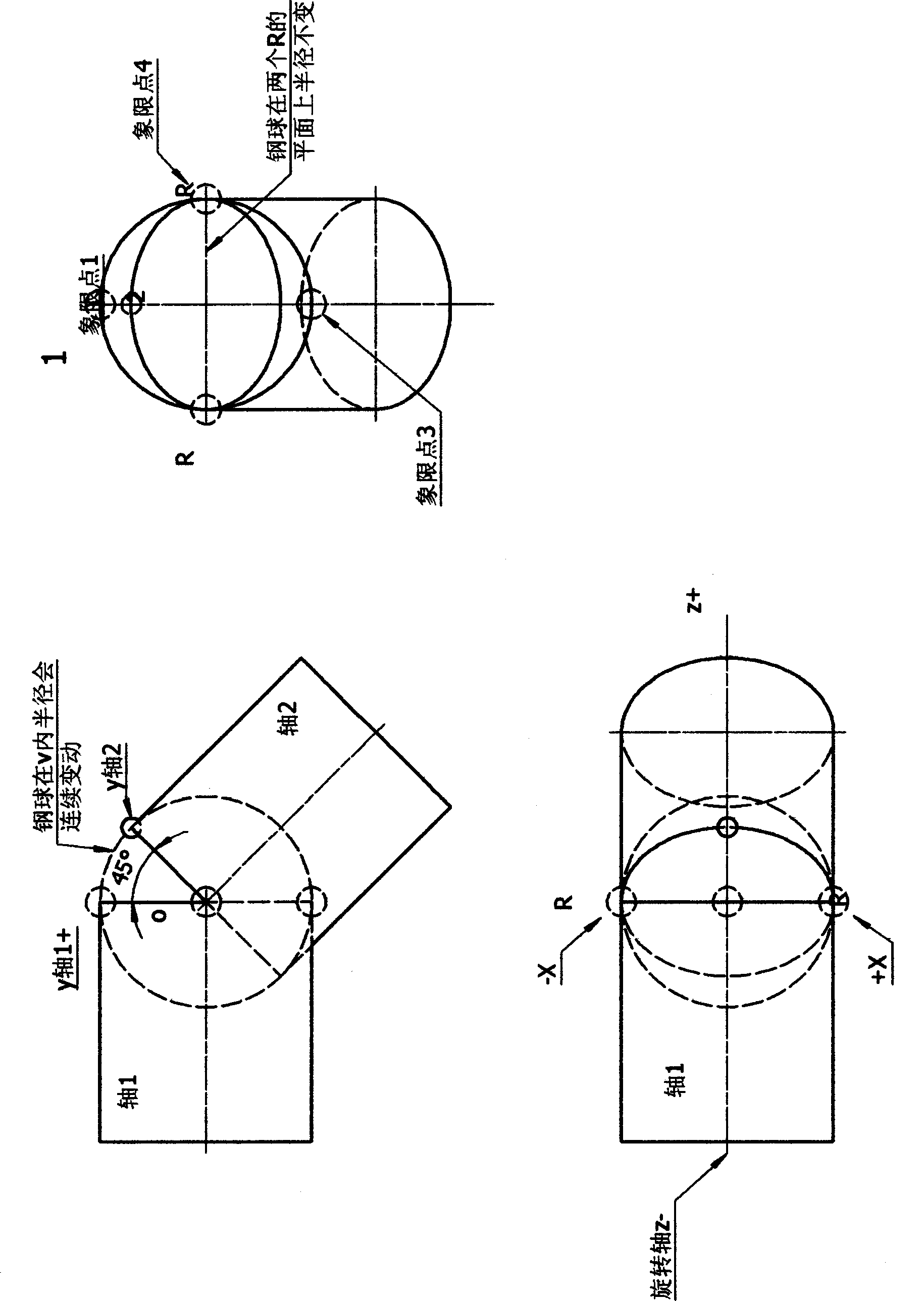
You can't see its trace in the movement of the two-dimensional plane, but in the three-dimensional model, it rotates synchronously with axis 1 and axis 2, and Y axis 3 rotates around Y axis 1 between zero and 180 degrees. Then make a turn around the Y axis 2 between 180 and 360 degrees, at least not considered beneficial

Method used


Image

  • Directional constant velocity ball cage universal joint
  • Directional constant velocity ball cage universal joint
  • Directional constant velocity ball cage universal joint

Examples


Embodiment Construction

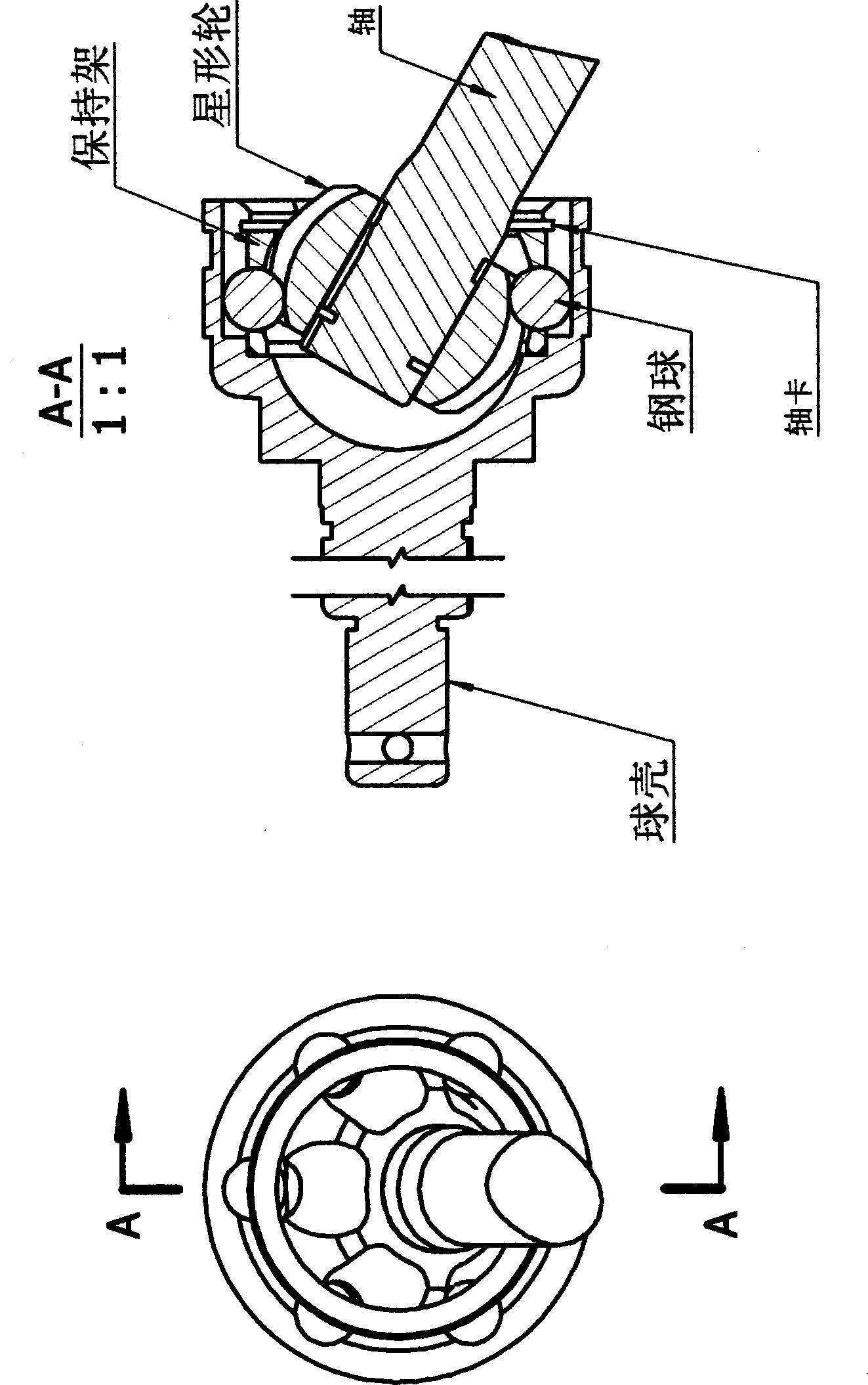
[0027] figure 1 ; The main feature of the directional ball cage is the fixed steel ball and the curved space raceway. After assembly, the concentricity of the main and driven shafts is guaranteed by the inner circle of the cage and the steel ball hole. The finished product has been statically twisted at the National Heavy-duty Vehicle Quality Supervision and Inspection Center. At 1960mn, the connecting flange with the torque machine will be twisted. The product is a miniature spherical cage with a maximum diameter of 50mm and a steel ball of 8mm. Report number;

[0028] 07-WT-DBJ-N059. In addition, at any steering angle on the inertial test bench, it can be pulled for a while and then slowly stop under inertia. Other universal joints and ball cages cannot.


PUM


Abstract

The invention provides a novel directional constant velocity ball cage universal joint. A steel ball is fixed on the central line of the input end, and a space track is customized according to a periodic time to be used as the output end. The time and space switching principle is applied, a directional track is overlapped on the steel ball, and therefore a speed equal to the input speed is obtained. The geometric principle of the novel directional constant velocity ball cage universal joint is that a three-dimensional ball is stable and can not move in a three-dimensional mode, three-dimensional movement is generated in a four-dimensional space, the fourth dimension is time, and walking space of the steel ball is made according to the periodic time. The overall path of the novel directional ball cage constant velocity universal joint is a Mobius ring, and the novel directional constant velocity ball cage universal joint turns four times and goes in the reverse direction two times in the process to transfer the turning included angle to a spherical surface. A directional ball cage operates in a three-dimensional mode, and the feature, changing obviously, of the ball cage is that the size and the weight of the ball cage can be lowered by 40%. The output mode of the directional constant velocity ball cage universal joint is that the front face and the back face act in a coupling mode, the contact effect and the bearing capacity both are increased in a multiplied mode, the directional constant velocity ball cage universal joint has three complete degrees of freedom, and no matter how the turning included angle changes, the directional constant velocity ball cage universal joint can keep constant. A star gear works in a suspended mode, and self consumption can be basically eliminated.

Description

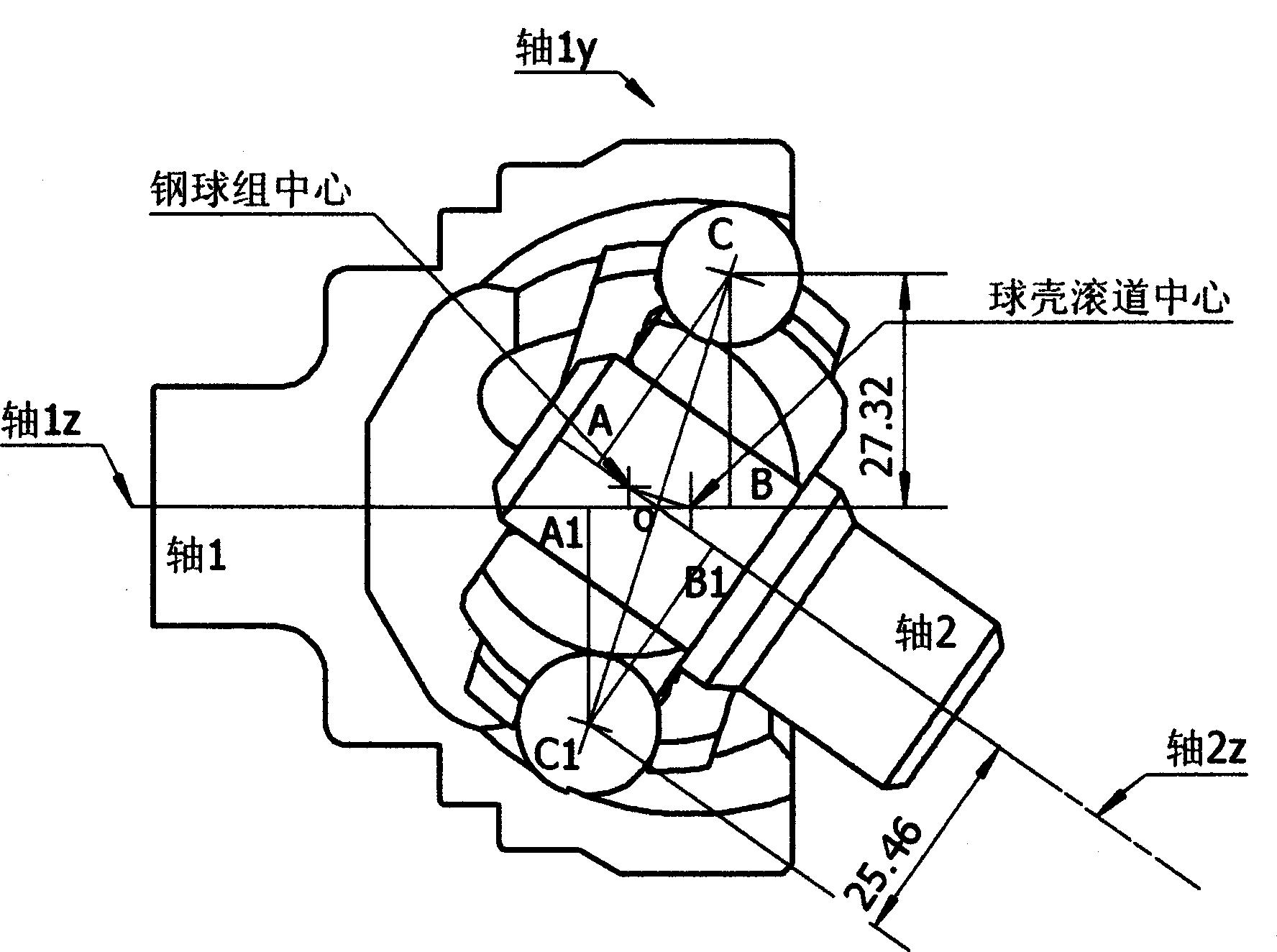
technical field [0001] The invention relates to a universal mechanical transmission component, a spherical cage type constant velocity universal joint, which is used to connect various power and loads between two shafts that are not on one axis, and is mainly used in passenger cars With various dynamic reversing transmissions. technical background [0002] Birfield constant velocity ball cage universal joint, according to its theory. When the angle α between the driving shaft and the driven shaft changes, the center of the force transmission steel ball is always located on the bisector of the angle between the two shafts, and the distance to the two axes is equal, ΔCOA≌ΔCOB, thus ensuring that the driving shaft and the driven shaft Rotate with equal angular velocity. [0003] The basis is derived from only one plane. There are four kinematic components of the isokinetic cage universal joint. The steel ball is the force transmission medium, and the cage is the commutator ...

Claims


Application Information

Patent Timeline
IPC IPC(8): F16D3/223
Inventor 丛滨江
Owner 丛滨江
Learn More