
Method for determining self-adaptive outline surrounding milling tool path according to peak characteristics of complex structural member

A technology for determining methods and structural parts, applied in the field of CNC machining of parts, can solve problems such as poor processing quality and low processing efficiency, and achieve the effects of improving processing quality, improving processing efficiency, and improving processing quality and processing efficiency

Active Publication Date: 2014-08-13
NANJING UNIV OF AERONAUTICS & ASTRONAUTICS
View PDF6 Cites 10 Cited by
  • Summary
  • Abstract
  • Description
  • Claims
  • Application Information

AI Technical Summary

Problems solved by technology

[0010] The purpose of the present invention is mainly to solve the problems of low processing efficiency and poor processing quality of the group peak features of complex structural parts in the numerical control machining process, and to invent a method for determining the tool path of complex structural part group peak features self-adaptive surround contour milling , to improve processing efficiency and processing quality

Method used


Image

  • Method for determining self-adaptive outline surrounding milling tool path according to peak characteristics of complex structural member
  • Method for determining self-adaptive outline surrounding milling tool path according to peak characteristics of complex structural member
  • Method for determining self-adaptive outline surrounding milling tool path according to peak characteristics of complex structural member

Examples


Embodiment Construction

[0047]The present invention will be further described below in conjunction with the accompanying drawings and embodiments.

[0048] Such as figure 1 ‐9.

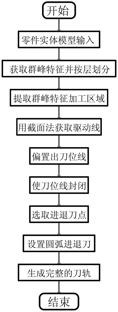
[0049] A tool path determination method for milling complex structural parts with group peak features around its contour, the whole steps are as follows figure 1 As shown, it includes the following ten steps:

[0050] Step 1. Input the solid model of the part and set the processing coordinate system.

[0051] Step 2. Obtain the group peak features and divide the group peak features into layers.

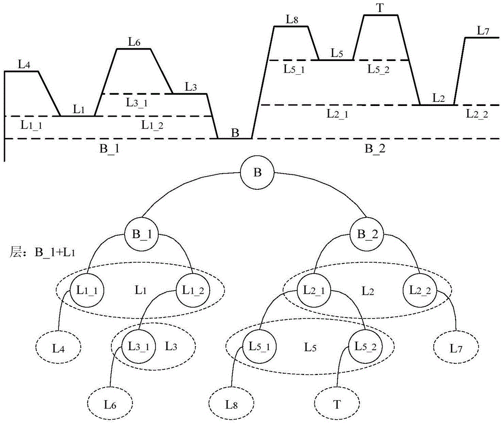
[0052] The peak characteristics of this embodiment are as Figure 8 As shown, the acquisition of the group peak features adopts the method of combining manual interaction and automatic identification: first, click the side in the part solid model to determine the group peak feature to be processed, and automatically identify other geometric features contained in the group peak feature according to the selected side. Elements,...


PUM


Abstract

A method for determining a self-adaptive outline surrounding milling tool path according to the peak characteristics of a complex structural member is characterized by including the steps of firstly, setting up a machining coordinate system of a part, obtaining the peak characteristics in the part, dividing the peak characteristics according to layers, and obtaining a machining area of each layer; secondly, obtaining a driving line of each layer through the method of sections, obtaining a tool position line for machining through the offset method, adding the required tool advancing and retracting mode, and generating the complete machining tool path. The milling tool path generated through the method is accurate, the tool void feeding route in the machining process can be reduced, machining efficiency of the part is improved, and meanwhile machining quality of the part can be improved.

Description

technical field [0001] The invention relates to a numerical control processing method for parts, in particular to a contour milling adaptive surround milling tool path calculation method for the peak characteristics of complex structural parts of an aircraft. The invention relates to a tool path calculation method for milling the outer contour shape of a body model, which belongs to the technical field of CAD / CAPP / CAM. Background technique [0002] With the rapid development of my country's aviation manufacturing technology, in the manufacture of modern aircraft, the application of CNC machine tools to process complex structural parts of aircraft is becoming more and more extensive. Aircraft complex structural parts are an important part of the aircraft body skeleton and aerodynamic shape. It has the characteristics of complex shape, large size, high processing precision, small rigidity, and difficult processing technology. The efficiency and quality of aircraft complex str...

Claims


Application Information

Patent Timeline
IPC IPC(8): G05B19/4097
Inventor 李迎光刘旭王鹏程李强
Owner NANJING UNIV OF AERONAUTICS & ASTRONAUTICS
Learn More