Transmission line patrol system and method based on optical transmission

A power transmission line and optical transmission technology, applied in the direction of overhead lines/cable equipment, etc., can solve the problems of immature robot line inspection technology, hidden safety hazards of urban line inspection, low line inspection accuracy, etc. The effect of easy interception and fast transmission speed

Active Publication Date: 2014-08-13
JINGJIANG POWER SUPPLY CO LTD JIANGSU ELECTRIC POWER
View PDF4 Cites 11 Cited by
  • Summary
  • Abstract
  • Description
  • Claims
  • Application Information

AI Technical Summary

Problems solved by technology

[0003] At present, most of the inspection methods commonly used for transmission lines are manual inspection, and some transmission systems use helicopter inspection. However, due to geographical and climatic conditions, and the inspection cost is high, there are great safety hazards in urban inspection.
However, robot line inspection has the defects of immature technology and high failure rate
For urban power transmission lines, manual inspection is still commonly used at present. If conventional methods such as naked eyes and telescopes are used to inspect the line, the inspection accuracy is low, labor-intensive, and the probability of missed detection is high.

Method used


Image

  • Transmission line patrol system and method based on optical transmission
  • Transmission line patrol system and method based on optical transmission
  • Transmission line patrol system and method based on optical transmission

Examples


Embodiment Construction

[0036] In order to further describe the technical features and effects of the present invention, the present invention will be further described below in conjunction with the accompanying drawings and specific embodiments.

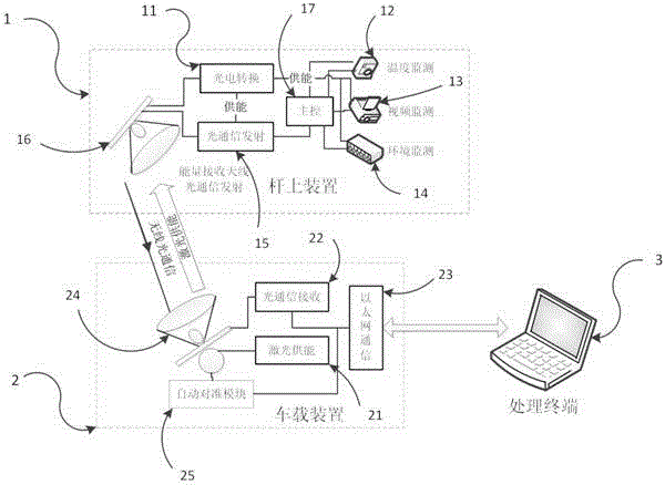
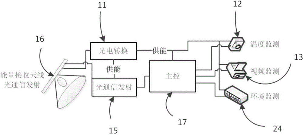
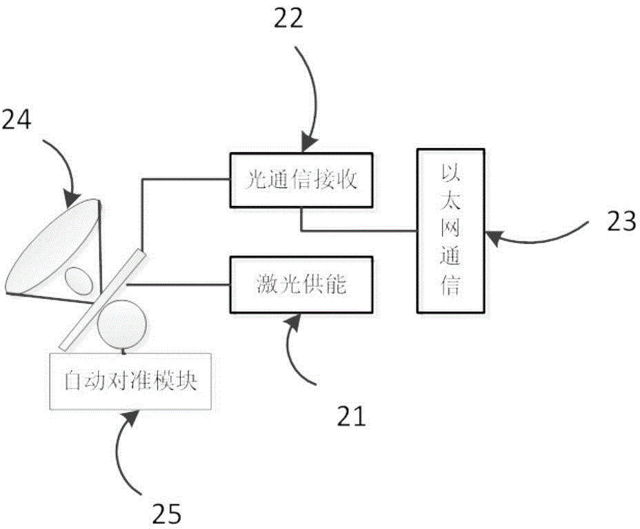
[0037] refer to Figure 1 to Figure 4 , a transmission line inspection system based on optical transmission, including a pole-mounted device 1 , a vehicle-mounted device 2 and a processing terminal 3 . The pole-mounted device 1 is set on the line pole tower and includes a laser energy receiving and converting module 11 , a temperature monitoring module 12 , a video monitoring module 13 , an environment monitoring module 14 , an optical communication transmitting module 15 , an antenna 16 on a pole and a main control module 17 . The vehicle-mounted device 2 is arranged on the line patrol vehicle, and includes a laser energy supply module 21, an optical communication receiving module 22, an Ethernet communication module 23, an on-board antenna 24 and an alig...


PUM


Abstract

The invention discloses a transmission line patrol system based on optical transmission. The transmission line patrol system comprises an on-pole device and a vehicle-mounted device. The on-pole device is arranged on a line pole tower and used for acquiring data of the temperature, images and the environment of a line and the line pole tower. The vehicle-mounted device is arranged on a line patrol vehicle and used for receiving data information acquired by the on-pole device and supplying energy to the on-pole device through lasers. The on-pole device sends the acquired data information to the vehicle-mounted device in a wireless optical communication mode, and the vehicle-mounted device transmits the received data information to a processing terminal for processing. Through laser energy supply and optical communication, electromagnetic interference is greatly reduced, battery energy supply is not needed, electricity does not need to be taken from the transmission line, and therefore the system is not in electrical connection with equipment on the detected line; the system is safer and more reliable, the cycle of overhaul and maintenance can be greatly prolonged, and signal confidentiality is high.

Description

technical field [0001] The invention relates to the technical field of power transmission line monitoring, in particular to a power transmission line inspection system based on optical transmission. Background technique [0002] With the development of society, the scale of cities is increasing day by day, and the electricity consumption capacity is constantly increasing. The voltage level of the urban power supply network is constantly increasing. However, with the gradual increase in the density of transmission corridors, higher and higher requirements are put forward for the safety and reliability of transmission lines. Therefore, the inspection of lines becomes particularly important. . [0003] At present, most of the inspection methods commonly used for transmission lines are manual inspection, and some transmission systems use helicopter inspection. However, due to geographical and climatic conditions, and the inspection cost is high, there are great safety hazards i...

Claims


Application Information

Patent Timeline
Patent Type & Authority Applications(China)
IPC IPC(8): H02G1/02
Inventor 陈凡刘海涛李先允李军
Owner JINGJIANG POWER SUPPLY CO LTD JIANGSU ELECTRIC POWER
Why Eureka
Try Eureka