Video compression collecting system and method

A technology of video compression and acquisition system, which is applied in digital video signal modification, electrical components, image communication, etc. It can solve problems such as difficulty in meeting video acquisition needs, inability to achieve continuous video acquisition, and large consumption of control information, so as to reduce data management. Burden, good resolution and data fidelity, motion blur removal effect

Inactive Publication Date: 2014-08-13
SUZHOU UNIV
View PDF6 Cites 6 Cited by
  • Summary
  • Abstract
  • Description
  • Claims
  • Application Information

AI Technical Summary

Problems solved by technology

However, the existing compressed imaging technology has the following defects: 1. The current compressed imaging technology is mainly used to realize the compression of imaging information in the spatial domain or frequency domain, but has not yet achieved the compression of information in the time dimension, which makes the existing Compressed imaging technology can only be used to collect discrete images, and cannot achieve continuous video acquisition. It is difficult to meet the high frame rate, especially the ultra-high frame rate video acquisition needs of existing applications; 2. Existing compressed imaging devices rely on space Optoelectronic devices such as optical modulators and digital micromirror devices can preprocess the optical information of the scene. The site selection and display control of the above-mentioned area array devices require a lot of control information.

Method used


Image

  • Video compression collecting system and method
  • Video compression collecting system and method

Examples


Embodiment 1

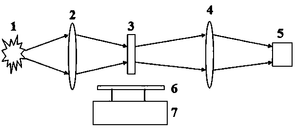
[0036] see attached figure 1 , which is a schematic structural diagram of a video compression, acquisition and imaging system provided in this embodiment. Place the video compression and acquisition system at an appropriate position right in front of the scene 1, and complete the alignment and focusing required for imaging; the scene 1 is imaged on the modulation surface of the passive optical signal modulation device 3 through the objective lens 2; the modulation of the modulation device The unit array (random binarization array is selected in this embodiment) implements amplitude modulation on the incident optical signal (transmissive modulation is selected in this embodiment), and the amplitude-modulated optical signal is then focused by the imaging lens 4 to the area array detector 5 on the focal plane. The theoretical maximum value of the video image sampling compression ratio of the video compression acquisition system is the ratio of the size of the modulation unit of ...


PUM


Abstract

The invention relates to a video compression collecting system and method. The video compression collecting system is used for imaging scenery on a modulation face of a passive light signal modulator through an objective, a high-precision displacement device is used for enabling the passive light signal modulator to generate a modulation effect with precise displacement and continuous conversion, video signals of the scenery are converted and modulated through the passive light signal modulator, and then integration and collection are conducted on the video signals through an area array detector. Compression image signals collected by the area array detector can be reconstructed, and original video signals of the scenery can be obtained. According to the video compression collecting method, an optical compression means is directly used for achieving parallel compression and collection of video data, and then original video data are reconstructed in a high-fidelity mode. According to the method, the video data collecting amount can be compressed in a large rate mode, the data management burden of video collection is relieved, and the method is particularly suitable for collecting high-resolution and high-frame frequency video signals.

Description

technical field [0001] The invention relates to a video compression imaging device and a video compression collection method, in particular to a video compression collection system and a video compression collection method. Background technique [0002] The application development of remote sensing imaging, machine vision, biological imaging and many other fields has put forward new requirements for the continuous acquisition technology of high frame rate and high resolution images. In the past ten years, with the continuous improvement of detector performance and image acquisition technology, the number of pixels in a single image of a digital camera has moved from the "mega" (million) level to the "giga" (billion) level. The frame rate has increased from 100 frames per second to 1000 frames per second to 10,000 frames per second, which enables the data rate of video obtained by high-frequency acquisition of large array images to reach the order of "Ai" (ten billion) pixels...

Claims


Application Information

Patent Timeline
IPC IPC(8): H04N19/48
Inventor 陈宇恒沈为民
Owner SUZHOU UNIV
Why Eureka
Try Eureka