

Magnesium alloy melt refining device
A refining device and technology for magnesium alloys, applied in the field of metal materials and metallurgy, can solve the problems of large bubble size, fast floating speed, large flux amount, etc., and achieve the effects of preventing oxidative combustion, reducing the moving speed and increasing the diffusion area.
Active Publication Date: 2014-08-20
NORTHEASTERN UNIV LIAONING
View PDF2 Cites 2 Cited by
- Summary
- Abstract
- Description
- Claims
- Application Information
AI Technical Summary
Problems solved by technology
At present, the industrial smelting of magnesium alloys mainly adopts flux refining method, filter filtration method and gas blowing method to achieve purification, but basically they are operated manually or with simple tools, so the amount of flux used in flux refining Relatively large, the pollution is also relatively large, and it is easy to produce flux inclusions; when the blowing method is used, the gas consumption is large and the cost is high
The bubbles generated by the blowing method are larger in size and faster in floating speed, which requires a longer degassing time, and the distribution in each area of the melt is uneven and cannot fully contact with the entire melt, and the degassing efficiency is low; The French filter is easy to react with the chemically active magnesium melt, so it cannot be used for a long time
Method used
View moreImage
Smart ImageViewing Examples

Examples
Embodiment
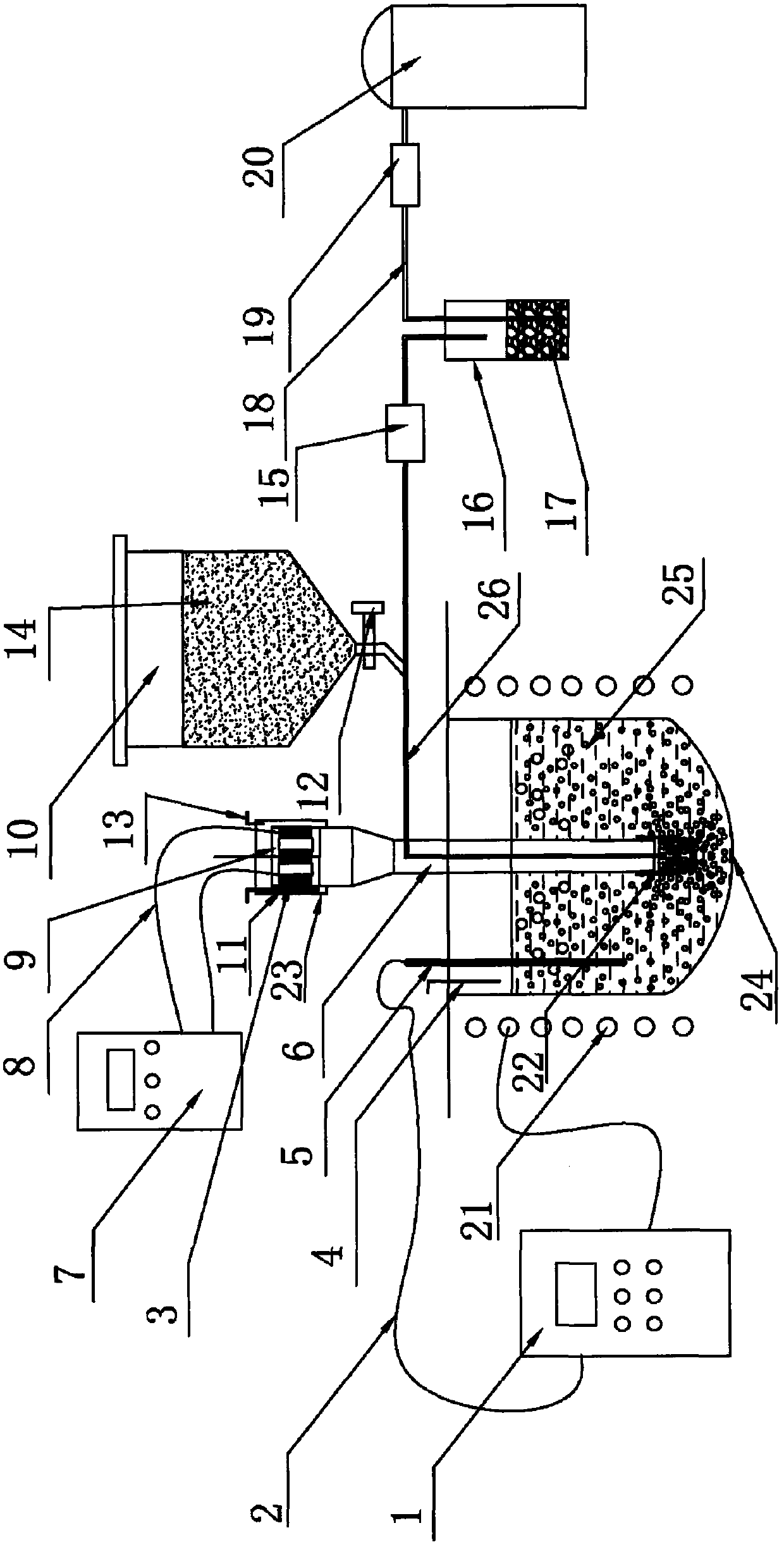
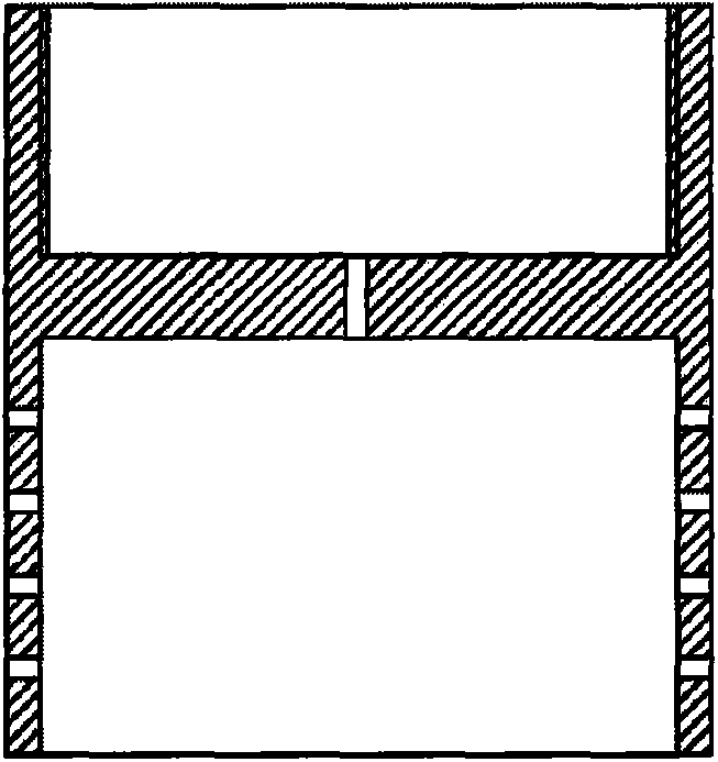
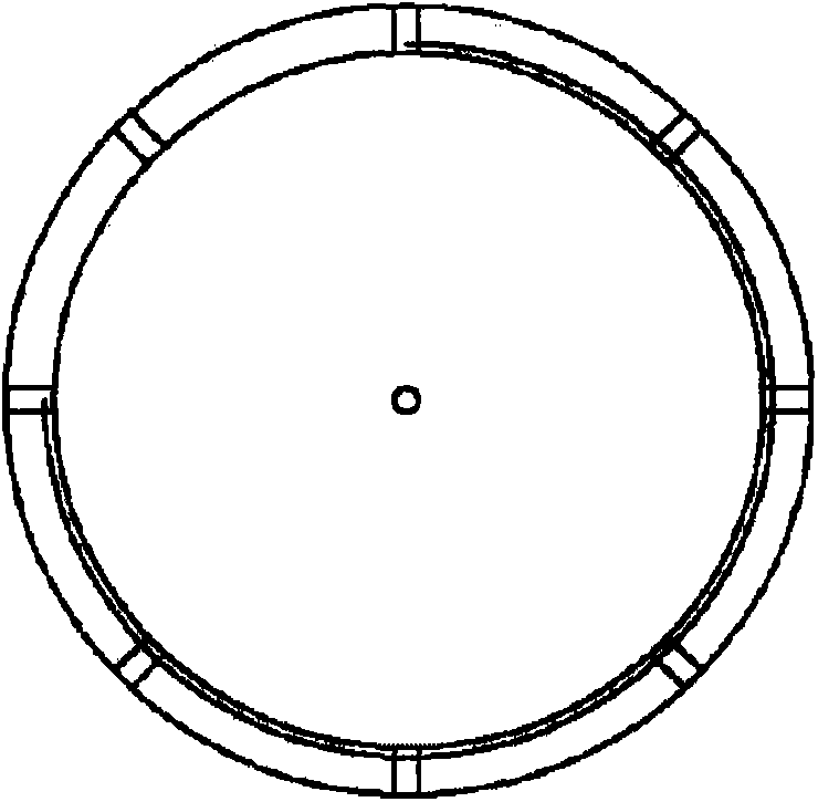
[0024] Utilize the device of the present invention to carry out purifying treatment to common commercial AZ91 magnesium alloy melt, the tool head structure in the device is as follows figure 2 As shown, the hole with a diameter of 0.7 mm is opened on the lower end wall of the tool head 22, and the number of holes on the wall is 10; the diameter of the air outlet on the end face of the tool head is 0.8 mm, and the number is 4; Medium melting, the melting temperature is 720°C. The tool head of the device of the invention was preheated to 720°C prior to processing.
Login to View More PUM
 Abstract
The invention relates to a magnesium alloy melt refining device mainly comprising four parts, namely a high-strength acoustic cavitation system, a quantitative flux supply system, an inert gas supply system and a melt heat preservation system.
Description
technical field [0001] The invention belongs to the technical field of metal materials and metallurgy, and in particular relates to a magnesium alloy melt refining device. Background technique [0002] Magnesium alloys are widely used in automobiles, communication equipment and It has broad application prospects in the electronics industry. However, due to the chemical properties of magnesium alloys and their liveliness, the affinity between magnesium and oxygen is much higher than that between aluminum and oxygen. During the melting process of magnesium alloys, it is very easy to chemically react with oxygen, nitrogen, and water vapor, resulting in a large number of inclusions. Magnesium The content of inclusions during smelting is as high as about 20 times that of aluminum alloy. In addition, due to the great solubility of hydrogen in magnesium alloy melts, the solubility of hydrogen in magnesium melts is two orders of magnitude larger than that in aluminum melts, and th...
Claims
Login to View More Application Information
Patent Timeline
 Patent Type & AuthorityApplications(China)
IPC IPC(8): C22C1/02C22C23/00C22B9/02C22B9/05
CPCY02P10/20
Inventor张志强乐启炽宝磊崔建忠
OwnerNORTHEASTERN UNIV LIAONING