Supercharge Your Innovation With Domain-Expert AI Agents!

Optical transceiver module

A technology of optical transceiver module and optical transmitter, which is applied in the field of optical communication, can solve problems such as easy detachment of optical fibers, reduction of installation accuracy of optical fibers, and poor coupling effect of optical transceiver modules, so as to achieve improved coupling effect, good optical fiber coupling effect, and smooth optical path The effect of high reliability

Active Publication Date: 2016-04-06
旭创科技有限公司
View PDF9 Cites 0 Cited by
  • Summary
  • Abstract
  • Description
  • Claims
  • Application Information

AI Technical Summary

Problems solved by technology

[0005] In the above structure, since a V-shaped groove is provided on the substrate, it is difficult for the V-shaped groove to accurately match the outer diameter of the optical fiber, and the optical fiber is easy to fall off the V-shaped groove during the fixing process, so it is difficult to accurately control the fixed position of the optical fiber. , which reduces the installation accuracy of the optical fiber, resulting in poor coupling effect of the optical transceiver module

Method used


Image

  • Optical transceiver module
  • Optical transceiver module
  • Optical transceiver module

Examples


Embodiment Construction

[0035] The present invention will be described in detail below with reference to the specific embodiments shown in the accompanying drawings. However, these embodiments do not limit the present invention, and structural, method, or functional changes made by those skilled in the art according to these embodiments are all included in the protection scope of the present invention.

[0036] For the convenience of description, the operator's observation angle is taken as the reference direction for detailed description, and the upper, lower, left and right appearing below are all reference angles.

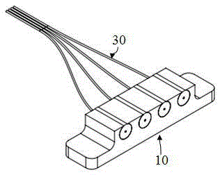
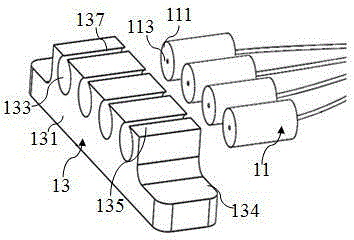
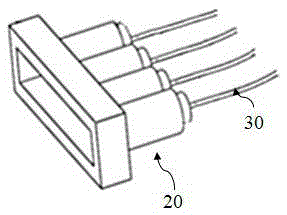
[0037] The optical transceiver module includes a housing, a circuit board provided in the housing, a light emitting component and / or a light receiving component (not shown in detail), the light emitting component includes an optical transmitter and a light exit interface, and the light receiving component includes The optical receiver and the incoming light interface, between the optic...


PUM


Abstract

The present invention provides an optical transceiver module, including an optical fiber, and an optical fiber positioning structure for fixing the optical fiber, the optical fiber includes a first positioning member for fixing the optical fiber and fixing the first positioning member on the housing The first support member; the first positioning member includes a first end surface and a second end surface oppositely arranged, and a first through hole communicating with the first end surface and the second end surface, and the first through hole The aperture is equivalent to the diameter of the optical fiber, and the optical fiber is fixed in the first through hole; the first support member is provided with an accommodating portion for the first positioning member, and the first positioning member is fixed on the housing. Compared with the prior art, the optical transceiver module provided by the present invention includes an optical fiber positioning structure. The optical fiber positioning structure has a more reasonable structure, and can more accurately locate the optical fiber in the optical transceiver module. Further, it improves the optical fiber positioning structure. The stability of the optical path transmission in the optical transceiver module of the positioning structure.

Description

technical field [0001] The invention relates to the field of optical communication, in particular to an optical transceiver module. Background technique [0002] With the development of science and technology, high-speed signal transmission technology has been widely used. Optical interconnection can transmit signals in a much wider bandwidth than electrical transmission, and use small-sized, low-power optical transceiver modules to construct signal transmission systems. Therefore, high-speed signal transmission technology has turned attention to optical interconnection as a signal transmission technology between devices. Accordingly, optical transceiver modules mounted on computers, vehicles, etc. as electronic components are widely used. [0003] In the process of using the optical transceiver module, it is necessary to couple the optical fiber inside it with the chip, the lens, etc. at the transmitting end and / or the receiving end. Correspondingly, in order to achieve a...

Claims


Application Information

Patent Timeline
Patent Type & Authority Patents(China)
IPC IPC(8): G02B6/42
CPCG02B6/3644G02B6/4292G02B6/4243
Inventor 杜寅超王帅杰李伟龙施高鸿
Owner 旭创科技有限公司
Features
  • R&D
  • Intellectual Property
  • Life Sciences
  • Materials
  • Tech Scout
  • Unparalleled Data Quality
  • Higher Quality Content
  • 60% Fewer Hallucinations
Learn More