Waste gas treatment system and treatment method for waste disposal

A technology for waste gas treatment and garbage treatment equipment, applied in separation methods, chemical instruments and methods, and separation of dispersed particles, can solve the problems of secondary air pollution and insufficient stable and effective treatment effects, and achieve stable effects

Inactive Publication Date: 2016-03-30
杨新玉
View PDF5 Cites 0 Cited by
  • Summary
  • Abstract
  • Description
  • Claims
  • Application Information

AI Technical Summary

Problems solved by technology

[0003] At present, the treatment of garbage waste gas is generally treated by spray neutralization acid-base method and ionization method, or by adding chlorine gas for oxidation reaction, but it is difficult to kill waste gas such as organic compounds and heavy metal ions through acid-base neutralization or oxidation reaction. Because the treatment effect is not stable and effective enough, the problem of secondary air pollution is more serious. Some urban residents have begun to protest collectively to prevent the construction of such waste such as incineration treatment plants near their homes, and a large amount of municipal solid waste has not yet been There are better ways to deal with it. At present, there are only four methods: incineration, biochemical, anaerobic, and electrolysis. For this reason, we have invented an electrolysis method to deal with the waste gas generated during the waste treatment process, which can truly realize the treatment. The waste gas emission generated by the garbage process meets the national standard, and the effect is stable

Method used


Image

  • Waste gas treatment system and treatment method for waste disposal

Examples


Embodiment 1

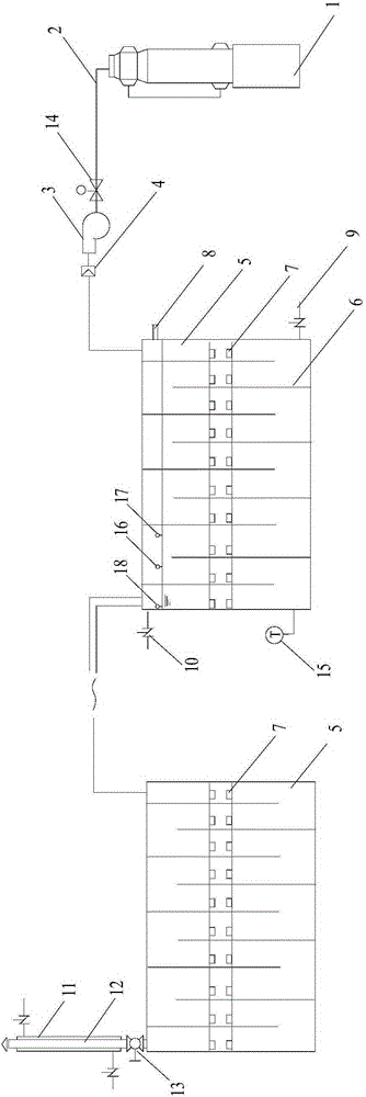
[0034] See figure 1 . Set the salt concentration to 3% PH to 3-4 voltage to 24V and current density to 1000A / m 2 The exhaust gas treatment system produced by various garbage treatment processes, the exhaust gas treatment system includes 20 pressure-bearing electrolytic brine tanks 5 ( figure 1 Only the first and the last one are shown in ), the pressure-bearing electrolytic brine tank 5 is a rectangular container, and N partitions are vertically placed in the pressure-bearing electrolytic brine tank 5, N=81 partitions ( figure 1 are omitted in ), divide the inside of the pressurized electrolytic brine tank into N-1 cavities of equal volume; N is an odd number of partitions that are connected to the top of the pressurized electrolytic brine tank and do not touch the bottom of the pressurized electrolytic brine tank, and N is The even-numbered partitions are connected to the bottom of the pressure-bearing electrolytic brine tank and do not touch the top of the pressure-bearing...

Embodiment 2

[0039] Adopt the waste gas treatment system with the same structure as in Example 1, place pure water with a concentration of 0wt% in the pressurized electrolytic brine tank, the positive and negative plates are evenly distributed in each tank, and the total electrode area of ​​each tank is 88m 2 . The distance between the positive plate and the negative plate is 0.2cm, and the current density is 2200A / m 2 current, voltage 24V. In this embodiment, the garbage disposal device is an incinerator. The 800°C waste gas produced by waste incineration is passed into the waste gas treatment system under the pressure of 4 Pa ​​(ie, the pressure of the induced draft fan), and electrolysis occurs in the non-salt water tank. After continuous electrolysis reaction through 22 water tanks, the waste gas is discharged.

[0040] The pH value of the saline is adjusted to 8.6-9.5 with sodium hydroxide.

[0041] Every 5-24 hours of operation, change the polarity of the positive and negative pla...

Embodiment 3

[0044] Using the exhaust gas treatment system of Example 1, place brine with a concentration of 6wt% in the pressurized electrolytic brine tank, the distance between the positive plate and the negative plate is 1 cm, and the current density is 1400A / m 2 current, the positive and negative plates are evenly distributed in each slot, and the total electrode area of ​​each slot is 10m 2 . Positive and negative plate voltage 12V. In this embodiment, the garbage disposal device is a biochemical garbage disposal device. The exhaust gas produced by biochemical treatment is passed into the exhaust gas treatment system under the pressure of 2 Pa (ie, the pressure of the induced draft fan), electrolyzed in salt water, and then discharged.

[0045] The pH value of the saline is adjusted to 8.6-9.5 with sodium hydroxide.

[0046] Every 24 hours of operation, change the polarity of the positive and negative plates by changing the direction of the positive and negative power supply. Circ...


PUM


Abstract

The invention belongs to the field of garbage treatment, and provides a waste gas treating system. The system comprises 1-30 pressure-bearing electrolytic brine tanks which are connected in series, wherein the tops of the tanks are connected with a pipeline for discharging waste gas in a garbage treating process; the tanks are internally provided with N partition plates, the pressure-bearing electrolytic brine tanks are divided into isometric N-1 cavities, the partition plates with serial numbers being odd numbers are connected with the tops of the pressure-bearing electrolytic brine tanks and are not contacted with the bottoms of the pressure-bearing electrolytic brine tanks, the partition plates with serial numbers being even numbers are connected with the bottoms of the pressure-bearing electrolytic brine tanks and are not contacted with the tops of the pressure-bearing electrolytic brine tanks, and the pressure-bearing electrolytic brine tanks are internally horizontally provided with positive plates and negative plates. The system provided by the invention has the advantages that an electrolyzing method is adopted to treat waste gas generated by burning, electrolysis, anaerobic and biochemistry methods in the garbage treating process, the waste gas generated by the garbage treating process can be effectively treated, the discharged waste gas achieves the national standard, and the effect is stable.

Description

technical field [0001] The invention belongs to four methods of garbage incineration and electrolysis, anaerobic or biochemical treatment of domestic device garbage, one of which can be selected, and specifically relates to a treatment system and method for waste gas generated in the four ways of garbage treatment. Background technique [0002] Most of the current domestic waste treatment uses incineration, biochemical, electrolysis, and anaerobic methods for treatment, and various organic and inorganic waste gases will be generated during the treatment process, mainly NO, NO 2 and dioxin gas, which are more harmful to the environment, and the invention of an electrolysis method can convert various waste gases such as NO and SO 2 , HCI, NO 2 、C 14 h 4 Cl 4 o 2 Etc. and heavy metal ions are treated by electrolysis to meet various exhaust gas emission standards, which is of great environmental and social significance. [0003] At present, the treatment of garbage waste g...

Claims


Application Information

Patent Timeline
Patent Type & Authority Patents(China)
IPC IPC(8): B01D53/32
Inventor 佘远斌杨新玉
Owner 杨新玉
Why Eureka
Try Eureka