Jet-flow-guided laser-spark-electrolysis combined machining device

A combined processing and laser processing technology, applied in the field of structural devices, can solve the problems of no efficient and precise processing method for micro holes with countersunk heads, inability to directly process countersunk heads, and inability to achieve countersunk head accuracy, etc. Low roughness value and low cutting force

Inactive Publication Date: 2014-08-27
JIANGNAN UNIV
View PDF6 Cites 11 Cited by
  • Summary
  • Abstract
  • Description
  • Claims
  • Application Information

AI Technical Summary

Problems solved by technology

However, this technology does not provide an efficient and precise machining method for machining tiny holes with countersunk heads
When it is necessary to process tiny holes with tapered countersunk heads or special-shaped countersunk heads, the laser processing method cannot directly process the countersunk head, and the electrolytic processing method cannot achieve the precision required for countersunk head processing.

Method used


Image

  • Jet-flow-guided laser-spark-electrolysis combined machining device
  • Jet-flow-guided laser-spark-electrolysis combined machining device

Examples


Embodiment example 1

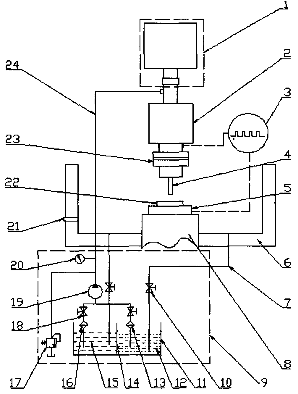
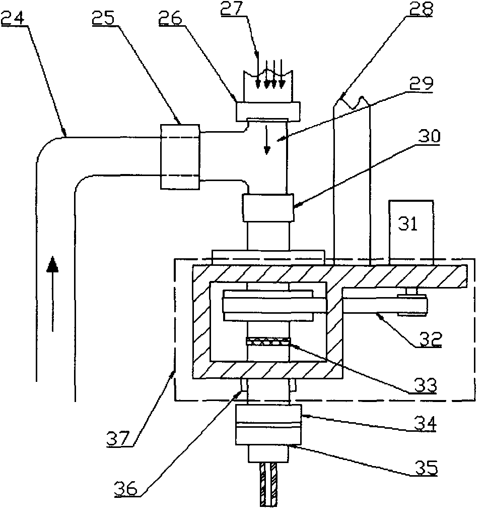
[0024]Implementation example 1: when the device of the present invention is in use, first, according to the actual processing needs, the tubular electrode 4 for electric discharge machining is installed on the electrode chuck 34 through the offline pre-adjustment of the electrode, so as to ensure that the tubular electrode 4 and the electrode chuck 35 have the same High coaxiality; then install the electrode torch 35 on the spindle chuck 34 to ensure that the electrode chuck 35 and the spindle chuck 34 have a very high coaxiality; thereby ensuring that the tubular electrode 4 for EDM and the laser beam 29 has extremely high coaxiality. After the above preparatory work is completed, the working fluid circulation system 9 starts to work, and the deionized water 12 passes through the deionization equipment 13, the switch valve (same as the electrolytic working fluid switch valve 18), the hydraulic pump 19, the hydraulic gauge 20, the liquid inlet pipe 24, The rotary joint 30 fina...

Embodiment example 2

[0025] Implementation example 2: The device of the present invention can adopt two processing combination methods of electric discharge machining and electrolytic machining when machining micro-grooves. Remove the working liquid inlet pipe 24 from the liquid inlet port 25, and then connect with the liquid inlet 21 on the processing tank 6 to quickly provide the working liquid for EDM in the processing tank until the working liquid level is higher than the workpiece 22 After a certain distance from the surface, turn on the liquid return pipe switch 10 for EDM to form a working fluid circulation, turn on the power module and provide electric pulses for EDM for EDM, turn on the motor 31, and drive the tubular electrode 4 to rotate through the timing belt 32 , and use the tubular electrode 4 to perform layer-by-layer electric discharge milling on the fine grooves. Subsequently, the working fluid is replaced, and the electrolytic working fluid 15 passes through the filter device 16...


PUM


Abstract

The invention relates to a jet-flow-guided laser-spark-electrolysis combined machining device, and belongs to the field of non-traditional machining. The jet-flow-guided laser-spark-electrolysis combined machining device adopts the structure integrating three non-traditional machining methods, and is composed of a laser generator, a machining module, a working solution circulation system and a power supply module, wherein the laser generator is placed above the machining module, and laser beam machining and spark machining are ensured to be coaxial; an electrode in the machining module for sparking machining can be stationary or rotary; the working solutions for jet-flow-guided laser machining and spark machining employ deionized water, and form a set of working solution circulation system with the working solution for electrolytic machining. When the device is used for machining, the jet-flow-guided laser machining and spark machining are employed as the main means for removing material, being accompanied by electrolytic machining; speed, accuracy and surface quality of part manufacturing are all taken into consideration; thereby, rapid machining of various micro holes with abnormal countersunk heads, and various defects caused by using single non-traditional machining method are overcome.

Description

technical field [0001] The invention relates to a device for processing micro-holes, grooves and other structures, in particular, it is a jet-guiding laser-electric spark-electrolysis combined processing device. Background technique [0002] EDM, electrolytic machining and laser machining are processing techniques developed in the 1940s, 1950s and 1960s respectively. Due to their different advantages, they have developed rapidly. They are used in aerospace, weaponry, automobiles, Widely used in electronics, shipbuilding and other manufacturing industries. The three have their own distinct characteristics for the processing of small holes that widely exist in the above fields. There are two methods of EDM machining micro-holes, namely EDM perforation and high-speed EDM small hole machining. Compared with other methods, they have certain advantages in micro-hole machining: any conductive material can be processed without being affected by the strength of the workpiece materia...

Claims


Application Information

Patent Timeline
Patent Type & Authority Applications(China)
IPC IPC(8): B23H5/00B23H5/14
Inventor 孔令蕾蒋毅平雪良田媛
Owner JIANGNAN UNIV
Why Eureka
Try Eureka