
Micro component extension test device

A tensile test and micro-component technology, applied in the direction of applying repeated force/pulsation force to test the strength of materials, can solve the problems of expensive instruments, large dispersion of test data, and no longer applicable test methods and devices, so as to facilitate installation Reliable effect of debugging and clamping

Active Publication Date: 2014-08-27
HARBIN INST OF TECH
View PDF4 Cites 11 Cited by
  • Summary
  • Abstract
  • Description
  • Claims
  • Application Information

AI Technical Summary

Problems solved by technology

However, due to the small size of the sample, a series of technical difficulties such as the centering of micro-components, clamping, micro-displacement driving, and measurement of micro-load and micro-displacement make traditional testing methods and devices no longer applicable.
At present, there is no uniform standard for testing devices, and most of the testing devices have complex structures, the required instruments are very expensive, and the test data is highly dispersed.
How to minimize test errors, ensure accurate and consistent test results, improve test efficiency, and enable test data to be processed quickly for feedback monitoring or directly applied to production practice, these problems are difficulties that need to be overcome urgently for researchers is also a challenge

Method used


Image

  • Micro component extension test device
  • Micro component extension test device
  • Micro component extension test device

Examples


Embodiment Construction

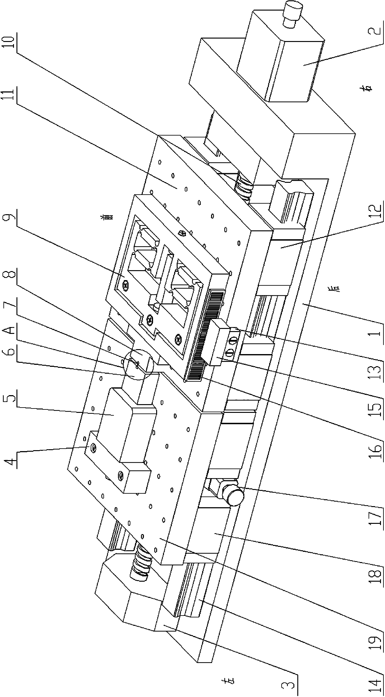
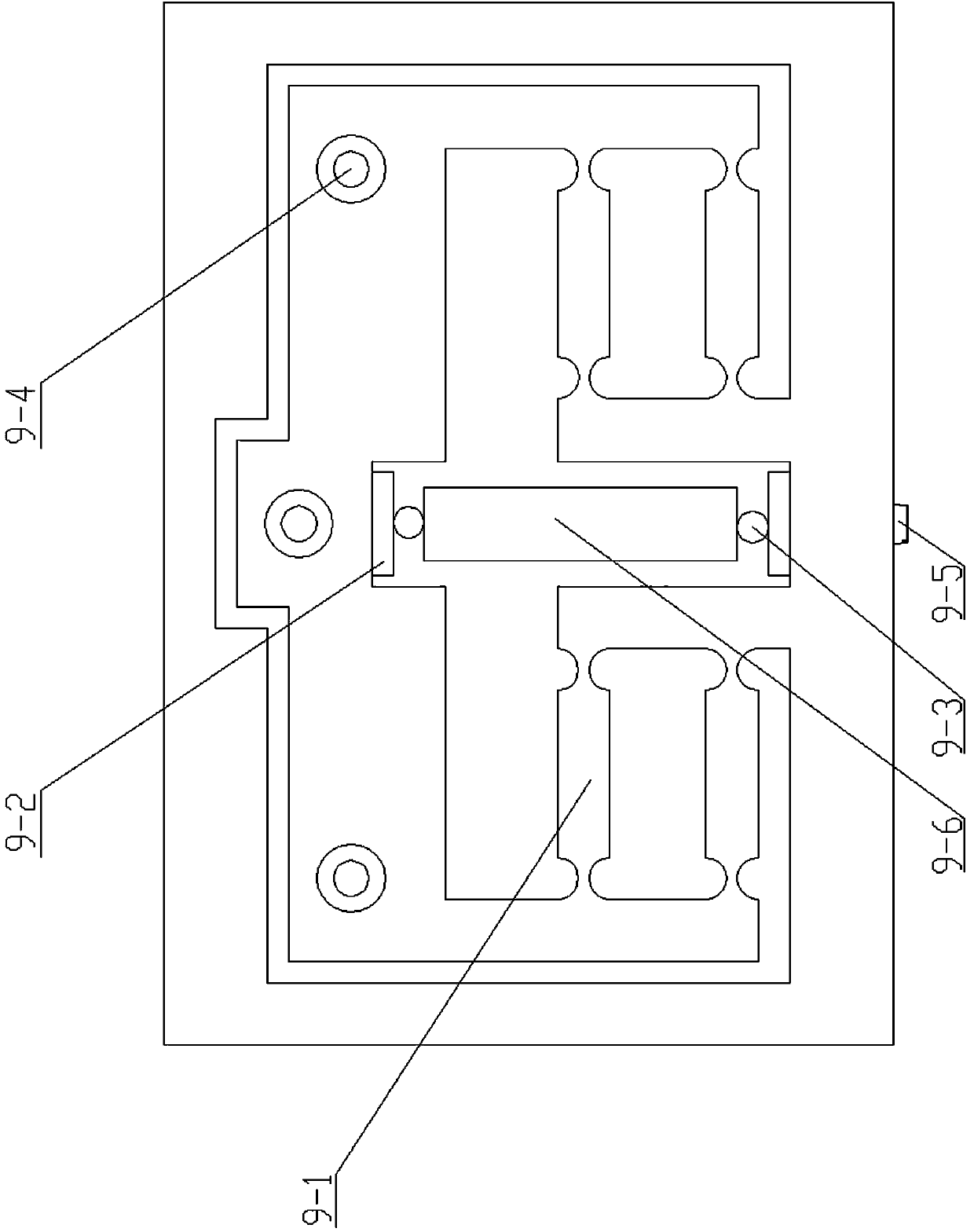
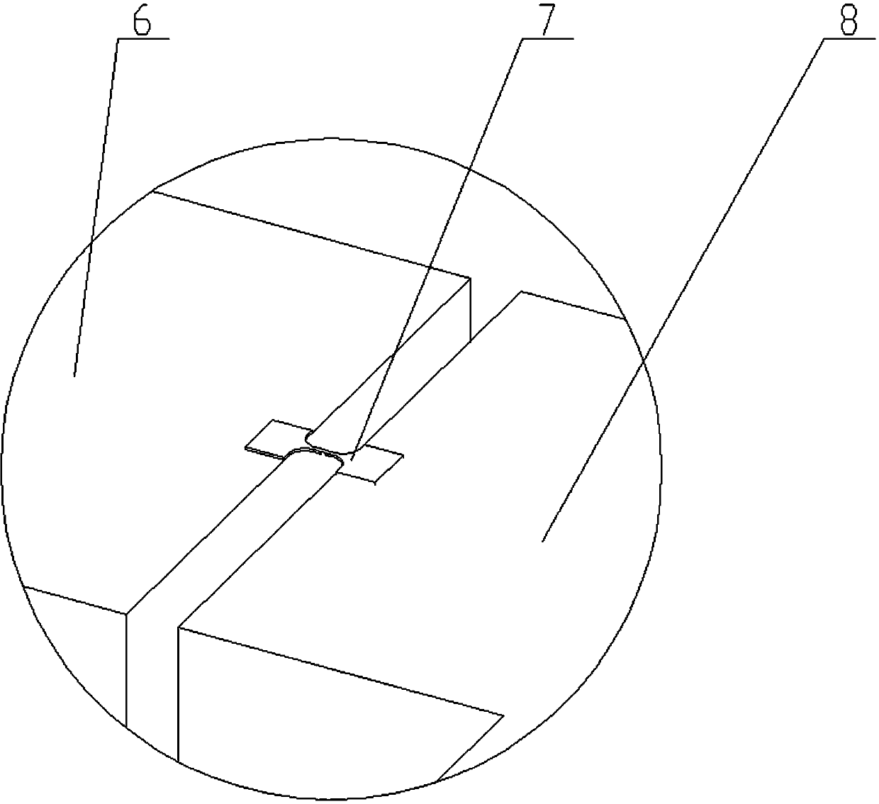
[0015] Such as Figure 1~Figure 3 As shown, the micro-component tensile testing device includes a precision drive unit 9, a micro force sensor 5, a linear grating measuring device, a high-precision electric shift stage, a stage, a force sensor fixing block 4, and two fixing parts 17. The high-precision electric moving stage includes a left loading platform 19, a right loading platform 11, a screw nut pair 10, an L-shaped base 1, a support base 3, a stepping motor 2, four left sliders 18, and four right sliders. Block 12, two guide rails 14, the described stage includes a moving stage 8 and a static stage 6, and the described linear grating measuring device includes a grating ruler reading head installation frame 13, a reading head 15 and a grating ruler 16 ,

[0016] The long plate of the L-shaped base 1 is arranged horizontally, and the two guide rails 14 are parallel to the long sides of the L-shaped base 1 and fixed on the long plate of the L-shaped base 1; the left loadin...


PUM


Abstract

The invention discloses a micro component extension test device, and relates to a micro component mechanical property test device. By means of the device, measurement of mechanical property static parameters of micrometer-scale components and exploration of the fatigue characteristic can be achieved. Two guide rails are fixed to an L-shaped base. A precise drive unit is fixed to a right object-carrying platform. A movable object-carrying platform is fixedly connected with the precise drive unit. A fixed object-carrying platform and the movable object-carrying platform are provided with positioning grooves for fixing micro components. The fixed object-carrying platform is fixedly connected with a micro force sensor which is fixedly connected with a force sensor fixing block. The force sensor fixing block is fixedly connected with a left object-carrying platform. A grating ruler is installed on the front side face or the rear side face of the precise drive unit. A reading head installation frame is fixed to the right object-carrying platform. A reading head is fixed to the reading head installation frame. The right object-carrying platform is fixedly connected with a lead screw nut of a lead screw nut pair. The right object-carrying platform is connected with the two guide rails in a sliding mode through four right slide blocks. A stepping motor drives the lead screw nut pair to move. The left object-carrying platform is fixed relative to the guide rails. The micro component extension test device is used for the micro component mechanical property test.

Description

technical field [0001] The invention relates to a device for testing the mechanical properties of micro components. Background technique [0002] The highly elastic alloy micro-components of the inertial navigation system are very easy to fracture and fail in the ground loading test, and the characteristic size of the micro-components in the inertial sensor is roughly in the range of submicron to millimeter. When it is micron / nanoscale, due to the size effect, the physical properties of the micro-component material itself and the degree to which it is affected by the environment will change greatly, and its mechanical properties and the relative relationship between the body force and surface force will also change. Significant changes will occur. The mechanical performance parameters of materials under macroscopic conditions are far from meeting the design requirements of MEMS system structures, and a series of technical problems caused by tiny test pieces make traditional...

Claims


Application Information

Patent Timeline
IPC IPC(8): G01N3/32
Inventor 车琳王波李国丁飞王石磊
Owner HARBIN INST OF TECH
Learn More