Imaging method for acceleratedly factorized back-projection bunching synthetic aperture radar

A technology of synthetic aperture radar and back projection, which is applied in the directions of radio wave reflection/re-radiation, utilization of re-radiation, measurement devices, etc., which can solve problems such as reduced computing efficiency, reduced image quality, and increased number of times

Inactive Publication Date: 2014-08-27
XIDIAN UNIV
View PDF2 Cites 29 Cited by
  • Summary
  • Abstract
  • Description
  • Claims
  • Application Information

AI Technical Summary

Problems solved by technology

However, two-dimensional (point-by-point) interpolation to achieve image fusion will cause two main problems: 1) The interpolation operation will inevitably introduce errors, and the errors will continue to accumulate and amplify as the recursive fusion proceeds, eventually causing image quality degradation. loss; 2) 2D interpolation is a very time-consuming part of the fast factorization backprojection method
When the number of apertures divided in the initial stage is small, the interpolation error accumulated by image recursive fusion is small, and the image quality is improved accordingly, but the corresponding calculation efficiency is reduced; and when the number of apertures divided in the initial stage is large, the number of image recursive fusion increases, the accumulated interpolation error is larger, and the image quality decreases accordingly

Method used


Image

  • Imaging method for acceleratedly factorized back-projection bunching synthetic aperture radar
  • Imaging method for acceleratedly factorized back-projection bunching synthetic aperture radar
  • Imaging method for acceleratedly factorized back-projection bunching synthetic aperture radar

Examples


Embodiment Construction

[0070] The present invention will be further described below in conjunction with accompanying drawing:

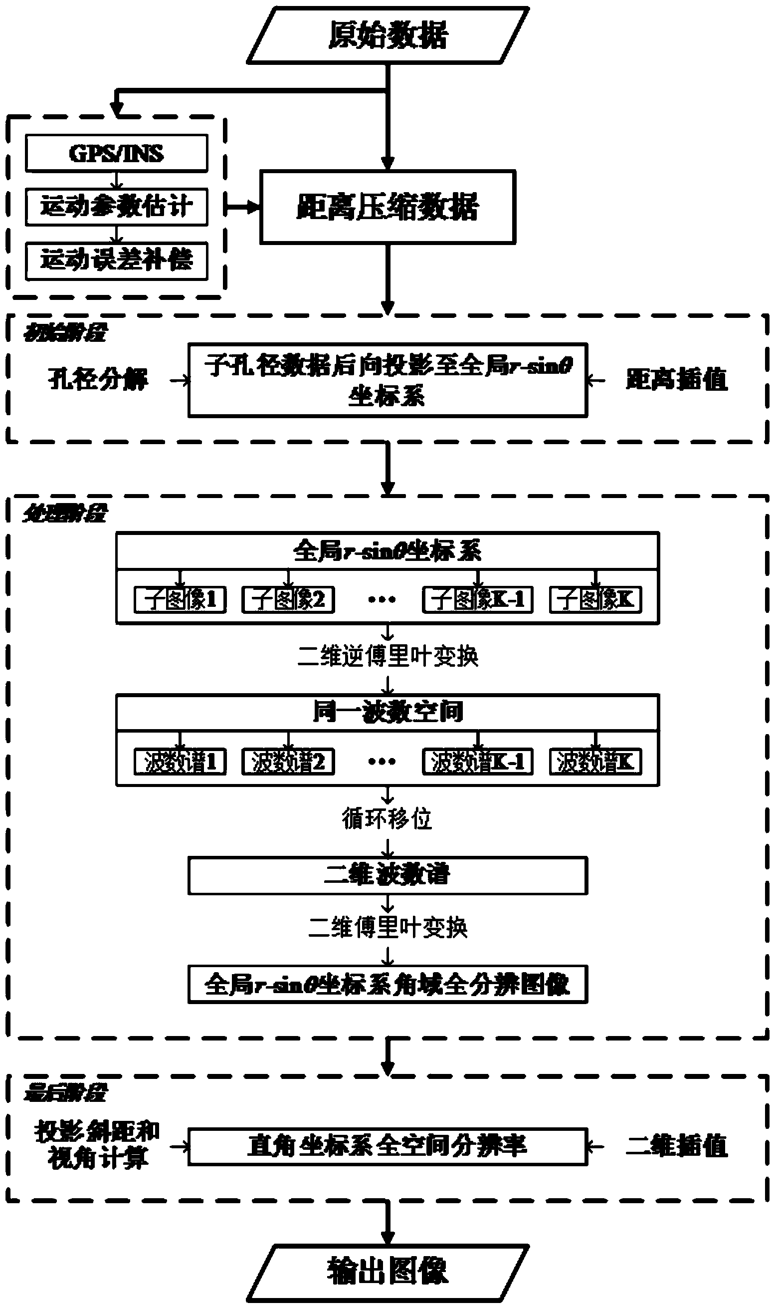
[0071] refer to figure 1 , is a flow chart of the accelerated decomposition backprojection spotlight synthetic aperture radar imaging method of the present invention. The accelerated decomposition back projection spotlight synthetic aperture radar imaging method includes the following steps:

[0072] S1: using the synthetic aperture radar on the moving platform to receive the echo signal, performing matching filtering on the echo signal, and obtaining the range pulse compression signal, and the moving platform is an aircraft or a satellite. The specific instructions are as follows:

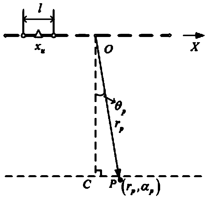
[0073] A synthetic aperture radar is installed on the moving platform. When the moving platform flies at a constant speed of v (the flying direction of the moving platform is expressed as the x direction), a synthetic aperture with a length of L is formed, and the center of the synthetic ape...


PUM


Abstract

The invention belongs to the technical field of the synthetic aperture radar imaging technology, and particularly relates to an imaging method for an acceleratedly factorized back-projection bunching synthetic aperture radar. The imaging method for the acceleratedly factorized back-projection bunching synthetic aperture radar includes the following steps that platform motion is used for forming a synthetic aperture, the center of the aperture is used as the original point to build a polar coordinate system (r, theta), and the whole aperture is divided into N0 isometric sub-apertures; it is set that alpha is equal to sin theta, and an impulse response function of a pixel point at the position of (rp, theta) corresponding to the uth sub-aperture is expressed as I (u) (alpha)=I (u) (rp, alpha); a two-dimensional wave number variable is defined; a two-dimensional wave number spectrum corresponding to the uth sub-aperture is obtained; according to two-dimensional wave number spectra corresponding to distance wave numbers, two-dimensional wave number spectra corresponding to all the sub-apertures are spliced in the azimuth direction, and one-dimensional wave number spectra corresponding to the distance wave numbers are obtained; then the one-dimensional wave number spectra corresponding to the distance wave numbers are spliced in the distance direction, and a two-dimensional wave number spectrum of the whole aperture is obtained; two-dimensional Fourier transformation is conducted on the two-dimensional wave number spectrum of the whole aperture, and a full spatial resolution image under the polar coordinate system is obtained.

Description

technical field [0001] The invention belongs to the technical field of synthetic aperture radar (SAR) imaging, and in particular relates to an imaging method for accelerated decomposition and backward projection beamforming synthetic aperture radar, which can be used for an airborne or spaceborne SAR imaging processing platform, and is suitable for nonlinear flight paths, large Strabismus and other complex imaging occasions. Background technique [0002] The back-projection (BP) method in time domain realizes the continuous accumulation of the energy of each pixel on the imaging grid through the integration along the slant distance history (called BP integration), which is an accurate spotlight SAR imaging algorithm. The time-domain back-projection method ideally solves the coupling problem of distance and azimuth, and is suitable for image reconstruction under complex imaging geometries such as large coherent accumulation angles or nonlinear flight paths, and the focused im...

Claims


Application Information

Patent Timeline
Patent Type & Authority Applications(China)
IPC IPC(8): G01S13/90
CPCG01S13/904G01S13/9047G01S13/9017
Inventor 张磊李浩林陈露露邢孟道
Owner XIDIAN UNIV
Why Eureka
Try Eureka