Light polarization beam splitter

A beam splitter and light polarization technology, which is applied to the coupling of optical waveguides and other directions, can solve the problems of increasing the difficulty and cost of processing, complex three-dimensional self-imaging effects, and small processing tolerances. Simple, small size effect

Active Publication Date: 2014-08-27
PEKING UNIV
View PDF4 Cites 19 Cited by
  • Summary
  • Abstract
  • Description
  • Claims
  • Application Information

AI Technical Summary

Problems solved by technology

The three-dimensional self-image effect is very complicated, so only two-dimensional self-image effect is used in general applications, that is, the thickness of the multimode waveguide can only support the design of one mode
Among them, the DC structure is the simplest, and the size of the plasmon can be made ultra-small, but the processing tolerance of both is very small, which increases the difficulty and cost of processing, and the device length is still on the order of microns; on the contrary, based on AWG , MMI, and MZI structure PBS can have a large tolerance, but AWG, MZI, and MMI are larger in size and more complex in structure, and the MMI type PBS using the quasi-imaging principle and other inferences based on the self-image effect will greatly reduce its Device size

Method used


Image

  • Light polarization beam splitter
  • Light polarization beam splitter
  • Light polarization beam splitter

Examples


Embodiment Construction

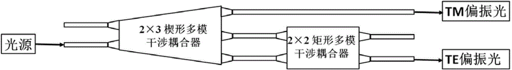
[0083] Below in conjunction with accompanying drawing, the present invention is described in further detail; Structural principle diagram of the present invention is as Figure 5 shown.

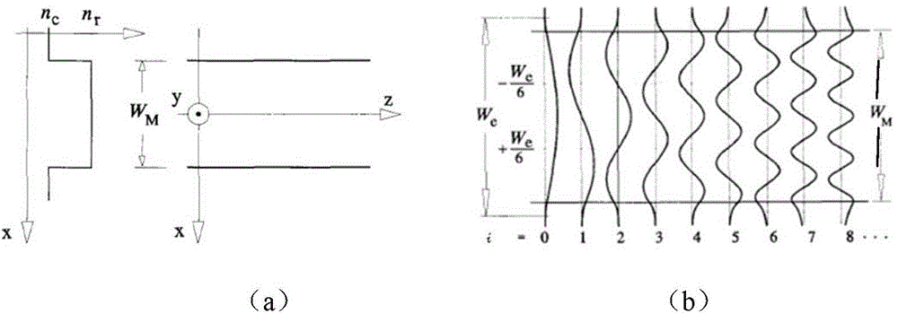
[0084] 1. TE and TM polarized light are input into the device at the same time, and propagate under multi-mode interference independently in the wedge-shaped multi-mode interference coupler;

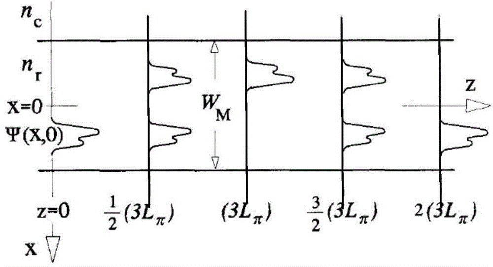
[0085] 2. Based on the principle of self-image effect, after the TM light forms a mirror point at point A, it is guided by the tapered waveguide and the straight waveguide to the TM light output port as a polarization beam splitter;

[0086] 3. Using overlapping imaging in the wedge-shaped MMI, TE light forms two overlapping imaging points at points B and C, which are guided by the tapered waveguide and the straight waveguide as the two inputs of the 2×2 rectangular multimode interference coupler;

[0087] 4. Taking silicon-on-insulator (SOI) material as an example, due to the design of the front and r...


PUM


Abstract

The invention discloses a light polarization beam splitter. The light polarization beam splitter comprises a wedge-shaped multi-mode interference coupler and a 2*2 rectangular multi-mode interference coupler. The wide end is provided with a first output port, a second output port and a third output port. The wedge-shaped multi-mode interference coupler meets the self-mapping effect principle and can produce mirror points in the first output port through TM light in an input light source and produce overlapping imaging points in the second output port and the third output port through TE light in the input light source, and the phase difference is 90 degrees. The first output port is connected with the coupling output end to serve as the TM light output port. The second output port and the third output port are connected with the first input end and the second input end of the rectangular multi-mode interference coupler through the coupler respectively. According to the rectangular multi-mode interference coupler, the port where the mirror point is produced through the input TE light serves as the TE light output port of the light polarization beam splitter. The light polarization beam splitter is small in size and easy to machine and has large machining tolerance and a high extinction ratio.

Description

technical field [0001] The invention relates to a waveguide optical polarization beam splitter comprising a multimode interference coupler, which belongs to the field of optical devices. Background technique [0002] In recent years, in waveguide structure optoelectronic devices, multimode interference coupler (MMI Coupler) has been increasingly used in integrated optical circuits due to its advantages of low loss, good balance, compact structure, large bandwidth, and large manufacturing tolerance. middle. Many MMI-based power splitters (combiners), mode converters, wavelength division multiplexers, ring semiconductor lasers, and optical switches have emerged. [0003] The self-image effect is an important characteristic of multimode waveguides. In 1973, the self-image effect of a uniform refractive index slab waveguide was first proposed, and on this basis, a multimode interference coupler was developed. The multimode interference coupler has simple manufacturing process...

Claims


Application Information

Patent Timeline
Patent Type & Authority Applications(China)
IPC IPC(8): G02B6/27
Inventor 杨威李艳萍王兴军王子宇
Owner PEKING UNIV
Why Eureka
Try Eureka