Fuel gasification system, control method and control program therefor, and fuel gasification combined power generation system provided with fuel gasification system

A fuel gasification and fuel technology, which is applied in the direction of granular/powder fuel gasification, gasification device feeding tools, fuel, etc., can solve the problem of difficult power generation and keeping constant, and achieve stable calorific value and suppress increase or decrease Effect

Inactive Publication Date: 2014-08-27
MITSUBISHI HEAVY IND LTD
View PDF5 Cites 4 Cited by
  • Summary
  • Abstract
  • Description
  • Claims
  • Application Information

AI Technical Summary

Problems solved by technology

Therefore, in the combined coal gasification power generation system using the compressor of the gas turbine unit as the supply source of air supplied to the gasifier, it is difficult to keep the power generation constant when the calorific value decreases.

Method used


Image

  • Fuel gasification system, control method and control program therefor, and fuel gasification combined power generation system provided with fuel gasification system
  • Fuel gasification system, control method and control program therefor, and fuel gasification combined power generation system provided with fuel gasification system
  • Fuel gasification system, control method and control program therefor, and fuel gasification combined power generation system provided with fuel gasification system

Examples


no. 1 Embodiment approach 〕

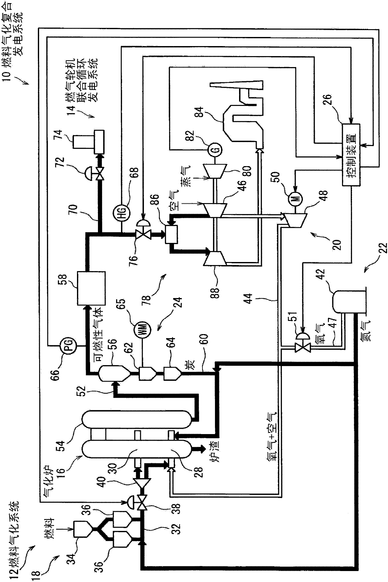
[0060] figure 1 A schematic configuration of a fuel gasification integrated power generation system (hereinafter, also referred to as IGCC) 10 according to the first embodiment is shown. In addition, when the fuel is coal, IGCC10 is a combined coal gasification power generation system.

[0061] The IGCC 10 is composed of a fuel gasification system 12 and a gas turbine combined cycle power generation system (hereinafter also referred to as GTCC) 14 . The fuel gasification system 12 gasifies fuel to generate combustible gas, and the GTCC 14 generates power using the combustible gas. In addition, when the fuel is coal, the fuel gasification system 12 is a coal gasification system.

[0062] 〔Fuel gasification system〕

[0063] The fuel gasification system 12 has a gasifier 16, a fuel supply device 18 for supplying coal as a fuel to the gasifier 16, an air supply device 20 for supplying air as an oxidizing agent to the gasifier 16, A high-oxygen-concentration oxidant supply devi...

no. 2 Embodiment approach 〕

[0171] Hereinafter, the second embodiment will be described.

[0172] The second embodiment is as Figure 8 as well as Figure 9 As shown, the configuration of the gasifier control unit 94 in the control device 26 is different from that of the first embodiment.

[0173] Specifically, first, instead of the detected value of the SG calorific value, the detected value of the amount of char generation is input from the meter 65 to the gasifier control unit 94 . Then, the fuel / high oxygen concentration oxidant flow rate command value correcting unit 110 includes a char generation amount target value setting unit 138 and a char generation amount deviation computing unit instead of the SG calorific value target value setting unit 124 and the SG calorific value deviation computing unit 126. 140.

[0174] The char generation amount target value setting unit 138 sets the char generation amount target value using an appropriate function (FX) or map data based on the corrected GID corr...

no. 3 Embodiment approach 〕

[0179] Hereinafter, a third embodiment will be described.

[0180] The third embodiment is as Figure 10 as well as Figure 11 As shown, the configuration of the gasifier control unit 94 in the control device 26 is different from that of the first embodiment.

[0181] Specifically, the gasifier control unit 94 of the third embodiment further includes a fuel flow rate additional correction amount setting unit 144, a fuel flow rate correction amount determination unit 146, a high oxygen concentration oxidant flow rate additional correction amount setting unit 148, and a high Oxygen concentration oxidant flow rate correction amount determination unit 150 .

[0182] The fuel flow rate additional correction amount setting unit 144 performs advance control. Specifically, the fuel flow rate additional correction amount setting unit 144 sets the fuel flow rate additional correction amount using an appropriate function (FX) based on the GID target value set by the GID target value s...


PUM


Abstract

Provided are a fuel gasification system, a control method and control program applied to the fuel gasification system, and a fuel gasification combined power generation system provided with the fuel gasification system, whereby flammable gas obtained by gasifying fuel generates a stable amount of heat while the amount of char generated is also prevented from increasing or decreasing even when the type or behavior of the fuel changes. A control device (26) of a fuel gasification system (12) controls the amount of fuel being supplied to a gasification furnace (16) in accordance with an index corresponding to the amount of heat generated by a flammable gas (an amount of heat generated by SG), and controls the amount of oxygen gas being supplied to the gasification furnace (16) so that the ratio of the amount of oxygen gas being supplied with respect to the amount of air being supplied to the gasification furnace (16) changes.

Description

technical field [0001] The present invention relates to a fuel gasification system, a control method and a control program applied to the fuel gasification system, and a fuel gasification combined power generation system equipped with the fuel gasification system. A technology that generates heat from combustible gases generated by gasification. Background technique [0002] In recent years, an Integrated Gasification Combined Cycle (IGCC: Integrated Gasification Combined Cycle) system has been developed and put into practical use. Compared with the existing coal-fired thermal power generation, the combined coal gasification power generation system has higher power generation efficiency and is environmentally friendly as a result. [0003] The combined coal gasification power generation system is composed of a coal gasification system and a gas turbine combined cycle power generation (GTCC: Gas Turbine Combined Cycle) system. [0004] The coal gasification system includes ...

Claims


Application Information

Patent Timeline
Patent Type & Authority Applications(China)
IPC IPC(8): C10J3/46C10J3/48
CPCY02E20/16C10J2300/0959C10J3/485C10J2300/1653F01K23/10C10J2300/1678C10J2300/093C10J3/723Y02E20/18C10J3/721F02C3/28C10J3/506C10L3/00F02C3/22
Inventor 堤孝则石井弘实藤井贵小山智规
Owner MITSUBISHI HEAVY IND LTD
Why Eureka
Try Eureka