Roadway marking method and roadway marking system based on radar detection

A roadway and radar technology, applied in the field of highway traffic control, can solve the problems of decreased utilization rate of highways, easy traffic accidents, and clear display of drivers

Inactive Publication Date: 2016-08-03
青海省交通工程咨询有限公司
View PDF5 Cites 0 Cited by
  • Summary
  • Abstract
  • Description
  • Claims
  • Application Information

AI Technical Summary

Problems solved by technology

[0002] In the existing road traffic control signal system, as well as in the existing auxiliary road traffic control system, such as traffic lights at intersections and red light camera systems, camera monitoring systems, electronic card information announcements, street lights, and radio station announcements, all are It is used for the control of traffic at plane intersections or in a local area, and it is set at a specific location. It cannot realize the long-distance, continuous, and dynamic display of the occupancy of the linear roadway, the driving status of the vehicle, and the distance between vehicles. When the atmospheric visibility conditions are bad, such as fog and haze, relying on vehicle lighting, street lights, existing highway signal systems and reflective signs cannot clearly show the direction of the roadway and the distance between vehicles to the driver. Due to the limitation of the driver's sight distance, it is impossible to know the road ahead in time, which is likely to cause traffic accidents; therefore, in foggy weather, it is usually followed by warning vehicles to slow down or close the road to avoid traffic accidents. This situation is common in high-speed roads. In road traffic; this will reduce the utilization rate of expressways and bring inconvenience to people's daily life and economic activities

Method used


Image

  • Roadway marking method and roadway marking system based on radar detection
  • Roadway marking method and roadway marking system based on radar detection
  • Roadway marking method and roadway marking system based on radar detection

Examples


Embodiment Construction

[0033] Embodiment of the present invention is described below with accompanying drawing as example:

[0034] This embodiment takes the roadway marking system using the wireless positioning system as the implementation object to illustrate;

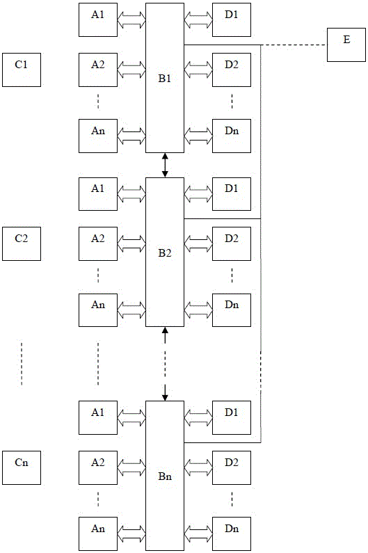
[0035] figure 1 It is a configuration diagram of a roadway marking system according to an embodiment of the present invention, wherein:

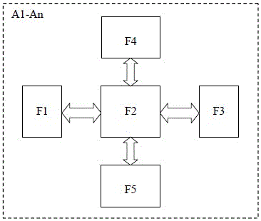
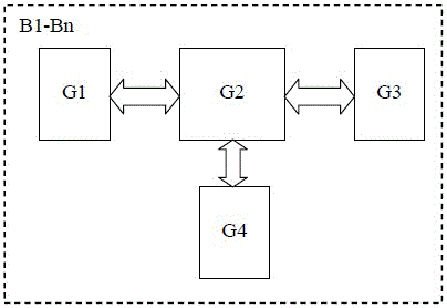
[0036] A1-An is the road signal, the road signal is arranged at a certain interval along the center line of each roadway, or arranged at a certain interval along the two sides of each roadway, that is, along the boundary line of each roadway and the edge of each roadway Lines are arranged at certain intervals to set up road signals; B1-Bn are satellite positioning and calibration repeating stations, which are set at certain intervals along the road line, and their communication ranges are linked to each other and cover all lanes of the entire road surface; C1-Cn D1-Dn are intelligent road traffic sign...


PUM


Abstract

The invention introduces a roadway marking system based on radar detection realized by a roadway marking system composed of a vehicle-mounted signal machine, a road surface signal machine, an intelligent road traffic sign, a data transmission and forwarding station, a central monitor, and a communication transmission system. The marking method, in the fog and haze weather, can realize the roadway marking and vehicle approaching distance marking and forecasting of running vehicles on the roadway of the highway, and timely send out distant display warnings to driving vehicles to avoid accidents and achieve auxiliary The purpose of driving safely and improving the utilization rate of expressways is that it is easy to implement and has strong practicability.

Description

technical field [0001] The invention relates to a roadway marking method and a roadway marking system based on radar detection, belonging to the field of road traffic control. Background technique [0002] In the existing road traffic control signal system, as well as in the existing auxiliary road traffic control system, such as traffic lights at intersections and red light camera systems, camera monitoring systems, electronic card information announcements, street lights, and radio station announcements, all are It is used for the control of traffic at plane intersections or in a local area, and it is set at a specific location. It cannot realize the long-distance, continuous, and dynamic display of the occupancy of the linear roadway, the driving status of the vehicle, and the distance between vehicles. When the atmospheric visibility conditions are bad, such as fog and haze, relying on vehicle lighting, street lights, existing highway signal systems and reflective signs ...

Claims


Application Information

Patent Timeline
Patent Type & Authority Patents(China)
IPC IPC(8): G08G1/0967
Inventor 张万庭许显贤王静徐维
Owner 青海省交通工程咨询有限公司
Why Eureka
Try Eureka