Control method of vehicle permanent magnet synchronous motor range extender

A technology of permanent magnet synchronous motor and control method, applied in the direction of motor, control drive, traction driven by engine, etc., can solve the problem that the capacity of the engine and generator cannot be used to the maximum, the remaining power of the battery is difficult, and the hardware cost and technology are increased. Complexity and other problems, to achieve the effect of rapid and accurate judgment process, avoid excessive discharge, and compact structure

Inactive Publication Date: 2014-09-10
BEIJING UNIV OF TECH
View PDF7 Cites 19 Cited by
  • Summary
  • Abstract
  • Description
  • Claims
  • Application Information

AI Technical Summary

Problems solved by technology

At present, there are many solutions for vehicle range extenders, but there are still problems, such as: some range extender products only use a constant power generation output, and cannot maximize the capacity of the engine and generator; The control method of the range extender needs to detect the remaining power of the battery, and the stroke of the accelerator pedal or the brake pedal of the vehicle needs to be detected to realize the judgment of the driver's driving intention, thereby determining the working mode of the range extender, as described in Patent No. CN102616148A. Detect remaining battery power and car pedal travel
However, it is difficult to accurately judge the remaining power of the battery, and the detection of the stroke of the accelerator pedal or brake pedal requires a special pedal, or the modification of the existing pedal of the vehicle, which increases the hardware cost and technical complexity

Method used


Image

  • Control method of vehicle permanent magnet synchronous motor range extender
  • Control method of vehicle permanent magnet synchronous motor range extender

Examples


Embodiment Construction

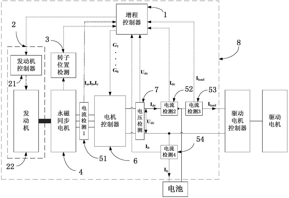
[0025] figure 1 It is a structural block diagram of a permanent magnet synchronous motor range extender for a vehicle. The range extender 8 is controlled by a range extender controller 1, an engine module 2, a rotor position detection 3, a permanent magnet synchronous motor 4, a current detection 1~451~54, and a motor Device 6, voltage detection 7 components. in:

[0026] The range extender controller 1 is mainly responsible for receiving signals such as various voltages and power supplies, and sends instructions to the motor controller 6 and the engine module 3 after processing, and its hardware carrier can be one or more of DSP, FPGA, ARM, and PLC combination.

[0027] The engine module 2 is composed of an engine controller 21 and an engine 22, and the engine controller 21 can be a mechanical controller or an electronic controller. The engine 22 may be a gasoline engine or a diesel engine.

[0028] The rotor position detection 3 is used to detect the current rotor positi...


PUM


Abstract

The invention provides a control method of a vehicle permanent magnet synchronous motor range extender and belongs to the technical field of the range extender control. A permanent magnet synchronous motor is used as either a starter or a generator, and is compact in structure, high in power density and high in power generation efficiency; no extra starting motor is needed so that the space and the cost can be saved; an engine always works in a high fuel efficiency rotating speed region. Meanwhile, the battery capacity, the driving intention of a driver and the drive demand are determined by use of the detection values of voltage and current sensors; the travel information of an accelerator or a brake pedal can be obtained without modifying the existing vehicle, and the determination process is quick and accurate. According to the power requirements of the whole vehicle, the range extender is capable of working in a plurality of modes, capable of effectively extending the vehicle miles of travel without affecting the power performance of the vehicle, and also capable of avoiding over-discharge of the battery and thus increasing the service life of the battery.

Description

technical field [0001] The invention relates to a vehicle range extender, in particular to a control method for a permanent magnet synchronous motor range extender. Background technique [0002] With the increasing shortage of oil resources in the world and the country's increasing emphasis on environmental protection, electric vehicles have received more and more attention. However, most of the electric vehicles on the market currently use batteries as the power source. Limited by the development of battery technology, the mileage of electric vehicles has not been able to meet people's expectations, and the battery life of electric vehicles is also shortened due to frequent deep discharge. decrease very much. [0003] The vehicle range extender can be directly connected to the power system of the vehicle, as an auxiliary power source, the engine drives the generator to generate electricity, and provides electric energy for the entire vehicle when the vehicle battery is ins...

Claims


Application Information

Patent Timeline
Patent Type & Authority Applications(China)
IPC IPC(8): B60L15/00B60L11/02B60L50/10
CPCY02T10/7077Y02T10/644Y02T10/64Y02T10/7072
Inventor 许家群吴跃乐戴佳奇
Owner BEIJING UNIV OF TECH
Why Eureka
Try Eureka