
A New Type of Tunnel Smooth Excavation Rock Drilling Equipment and Construction Method

A construction method and technology of rock drilling equipment, which are applied in the field of new tunnel smooth excavation rock drilling equipment and construction, can solve the problems of inability to be close to surrounding rock to achieve horizontal footage, increase safety risks in the support process, and large degree of rock mass damage and disturbance. problems, to achieve the effect of good work quality, convenient maintenance and reasonable oil circuit design

Active Publication Date: 2017-11-10
HUNAN MINGYI TUNNEL ENG TECH
View PDF9 Cites 0 Cited by
  • Summary
  • Abstract
  • Description
  • Claims
  • Application Information

AI Technical Summary

Problems solved by technology

At present, rock drills are widely used in engineering fields such as coal and mining. Using this equipment to drill holes in different rock masses lays the foundation for the subsequent installation of explosives. Traditional blasting technology is difficult to control the blasting intensity, and the degree of disturbance to the rock mass is large. , which is not conducive to the stability of the tunnel after excavation, resulting in a waste of manpower and material resources, and increasing the safety risk in the support process
[0003] The existing rock drilling machine lacks a horizontal plane, which affects the adjustment direction of the drill rod during excavation, and cannot be close to the surrounding rock to form a horizontal advance
Therefore, there are a large number of staggered stations between each drilling cycle, which increases the construction cost and increases the construction safety risk

Method used


Image

  • A New Type of Tunnel Smooth Excavation Rock Drilling Equipment and Construction Method
  • A New Type of Tunnel Smooth Excavation Rock Drilling Equipment and Construction Method
  • A New Type of Tunnel Smooth Excavation Rock Drilling Equipment and Construction Method

Examples


Embodiment Construction

[0024] In order to make it easy to understand the technical means, creative features, objectives and effects achieved by the present invention, the present invention will be further explained below in conjunction with specific drawings.

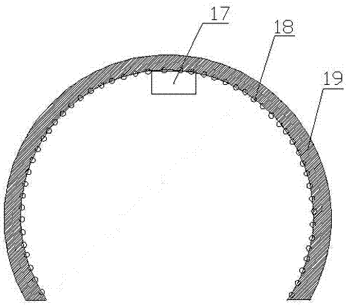
[0025] See figure 1 with figure 2 , A new type of tunnel smooth excavation rock drilling equipment, including shank (1), rotating sleeve (2), head (3), spline mother (4), bushing (5), guide sleeve (6) , Piston (7), screw rod (8), screw nut (9), valve (10), cylinder (11), ratchet (12), handle (13), long screw (15), nut (16), The upper end of the cylinder (11) is respectively connected with a handle (13) and a machine head (3) via a long screw (15) and a nut (16), and a guide sleeve (6) is provided on the inner wall of the left end of the cylinder (11) ), a bush (5) is provided on the inner wall of the guide sleeve (6), a piston (7) is provided in the cylinder (11), and a screw nut (9) is provided on the inner wall of the right end of the piston ...


PUM


Abstract

The invention provides novel tunnel smooth surface digging rock drilling equipment and a construction method of the novel tunnel smooth surface digging rock drilling equipment. The rock drilling equipment comprises a bit shank sleeve, a rotating sleeve, a machine head, a spline nut, a bushing, a guide sleeve, a piston, a spiral rod, a spiral nut, a valve, a cylinder body, a ratchet wheel, a handle, a long screw rod and a screw nut, wherein a silencing cap is arranged under the cylinder body. The construction method comprises the following steps of operation site cleaning, drilling point setting, air and water pipe connection for air and water supplying, hole drilling, slag cleaning, blasting, manual vaulting after danger elimination, and tunnel face guniting sealing. The silencing cap of the rock drilling equipment is arranged at the lower part of the cylinder body; during the hole drilling, the rock drilling equipment is tightly pasted on the peripheral rock at the upper surface of a blast hole as much as possible for operation; the gradient errors generated in the rock drilling feeding process is reduced to the maximum degree; the later-period support protection cost is greatly reduced; the matching dimensions of the rotating sleeve and the machine head, the piston and the cylinder body and the like are more reasonable; the flexibility of parts is maintained; and the noise in the moving process is also reduced.

Description

Technical field [0001] The invention relates to the technical field of tunnel excavation construction, in particular to a new type of tunnel smooth surface excavation rock drilling equipment and construction method. Background technique [0002] Rock drill is a machine for drilling holes in rocks. Its main working principle is to use compressed air as power to control the reciprocating movement of the piston through a passive valve. During the stroke, the piston impacts the drill tool to smash the rock. When returning, the piston drives the drill tool to rotate to a certain extent. The continuous impact and rotation make the drill drill a circular blast hole in the rock. At present, rock drills are widely used in coal, mining and other engineering fields. The equipment is used to perform drilling operations on different rock masses, laying the foundation for subsequent explosive installations. Traditional blasting techniques are difficult to control the blasting strength and caus...

Claims


Application Information

Patent Timeline
Patent Type & Authority Patents(China)
IPC IPC(8): E21D9/00
Inventor 胡铭益
Owner HUNAN MINGYI TUNNEL ENG TECH
Learn More