Solar heat storage type vacuum heat pipe

A technology of vacuum heat pipe and solar energy, which is applied in the field of solar heat utilization, can solve the problems of easy damage of glass, low heat balance temperature of heat dissipation area, no heat preservation ability, etc., and achieve the effects of enhanced heat absorption rate, reasonable structure design, and wide application range

Inactive Publication Date: 2014-09-10
南京百阳合能源科技有限公司
View PDF5 Cites 3 Cited by
  • Summary
  • Abstract
  • Description
  • Claims
  • Application Information

AI Technical Summary

Problems solved by technology

[0002] Solar thermal technology provides broad prospects for solving energy problems in the future. At present, solar water heaters mainly include high borosilicate glass vacuum tube type and high-efficiency heat-absorbing blue film flat plate type. The vacuum tube has been developed for more than 20 years and the coating process is very mature. From single target to Multi-target magnetron sputtering coating technology, the heat absorption efficiency of the film layer has reached more than 94%, and the low-temperature anti-reflection rate has reached below 6%, which is in a relatively ideal state. As long as the production process is strictly controlled according to the mature process, it can produce high-quality products. High vacuum tubes, vacuum tube water heaters have very good advantages, high absorption rate per unit area, low emissivity, good heat preservation, especially in colder areas, have unique advantages, but also have obvious disadvantages, can not be well combined with the building, subject to Due to the limitation of pipe diameter, the heat absorption area is small, and the heat absorption efficiency of double-layer glass is affected. The glass is easy to break and has inherent safety hazards. Therefo

Method used


Image

  • Solar heat storage type vacuum heat pipe
  • Solar heat storage type vacuum heat pipe

Examples


Example Embodiment

[0013] In the following, the present invention will be further clarified with reference to the accompanying drawings and specific embodiments. It should be understood that these embodiments are only used to illustrate the present invention and not to limit the scope of the present invention. After reading the present invention, those skilled in the art will understand various aspects of the present invention. Modifications in equivalent forms fall within the scope defined by the appended claims of this application.
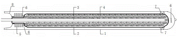
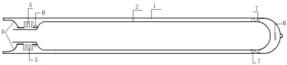
[0014] Such as figure 1 with figure 2 As shown, a solar heat storage type vacuum heat pipe includes an outer glass tube (1), an inner stainless steel tube (2) installed inside the outer glass tube (1), and an inner stainless steel tube (2) installed in the middle The heat pipe (3), the heat storage phase change material (4) filled between the inner stainless steel pipe (2) and the intermediate heat pipe (3), the expansion joint bellows (5) arranged at the end of the...


PUM


Abstract

The invention discloses a solar heat storage type vacuum heat pipe, comprising an outer-layer glass pipe (1), an inner stainless steel pipe (2) mounted in the outer-layer glass pipe (1), a middle heat conductive pipe (3) mounted in the inner stainless steel pipe (2), a heat storage phase-change material (4) filled between the inner stainless steel pipe (2) and the middle heat conductive pipe (3), expansion joint corrugated pipes (5) arranged at ends of the heat pipe, getters (6) arranged at two ends in the heat pipe, a stainless steel support frame (7) arranged between the outer-layer glass pipe (1) and the inner stainless steel pipe (2), and an inner glass pipe (8) butt jointed with the outer-layer glass pipe (1) and sealed with the same in a melting manner. The water heater provided by the invention is rational in structure design, free of water tanks, capable of being integrated with buildings, convenient to mount and maintain, high in safety factor, large in illuminating area, and high in heat absorption rate and stored heat energy, adopts the optimized heat storage phase-change material such that heat exchange can be performed according to requirements, can obtain fresh hot water upon using, and is wide in application range.

Description

technical field [0001] The invention relates to the field of solar heat utilization, in particular to a solar heat storage type vacuum heat pipe for a solar water heater. Background technique [0002] Solar thermal technology provides broad prospects for solving energy problems in the future. At present, solar water heaters mainly include high borosilicate glass vacuum tube type and high-efficiency heat-absorbing blue film flat plate type. The vacuum tube has been developed for more than 20 years and the coating process is very mature. From single target to Multi-target magnetron sputtering coating technology, the heat absorption efficiency of the film layer has reached more than 94%, and the low-temperature anti-reflection rate has reached below 6%, which is in a relatively ideal state. As long as the production process is strictly controlled according to the mature process, it can produce high-quality products. High vacuum tubes, vacuum tube water heaters have very good ad...

Claims


Application Information

Patent Timeline
IPC IPC(8): F24J2/46F24J2/48C09K5/06
CPCY02E10/40
Inventor 孙希干
Owner 南京百阳合能源科技有限公司
Why Eureka
Try Eureka