
Current mode bandgap reference voltage source with subthreshold current compensation function
A sub-threshold current and reference voltage source technology, applied in the direction of adjusting electrical variables, control/regulating systems, instruments, etc., can solve the problem of no compensation in the low temperature section, and achieve the effect of flexible design, simple structure and small footprint
- Summary
- Abstract
- Description
- Claims
- Application Information
AI Technical Summary
Problems solved by technology
Method used
Image

Examples
Embodiment Construction
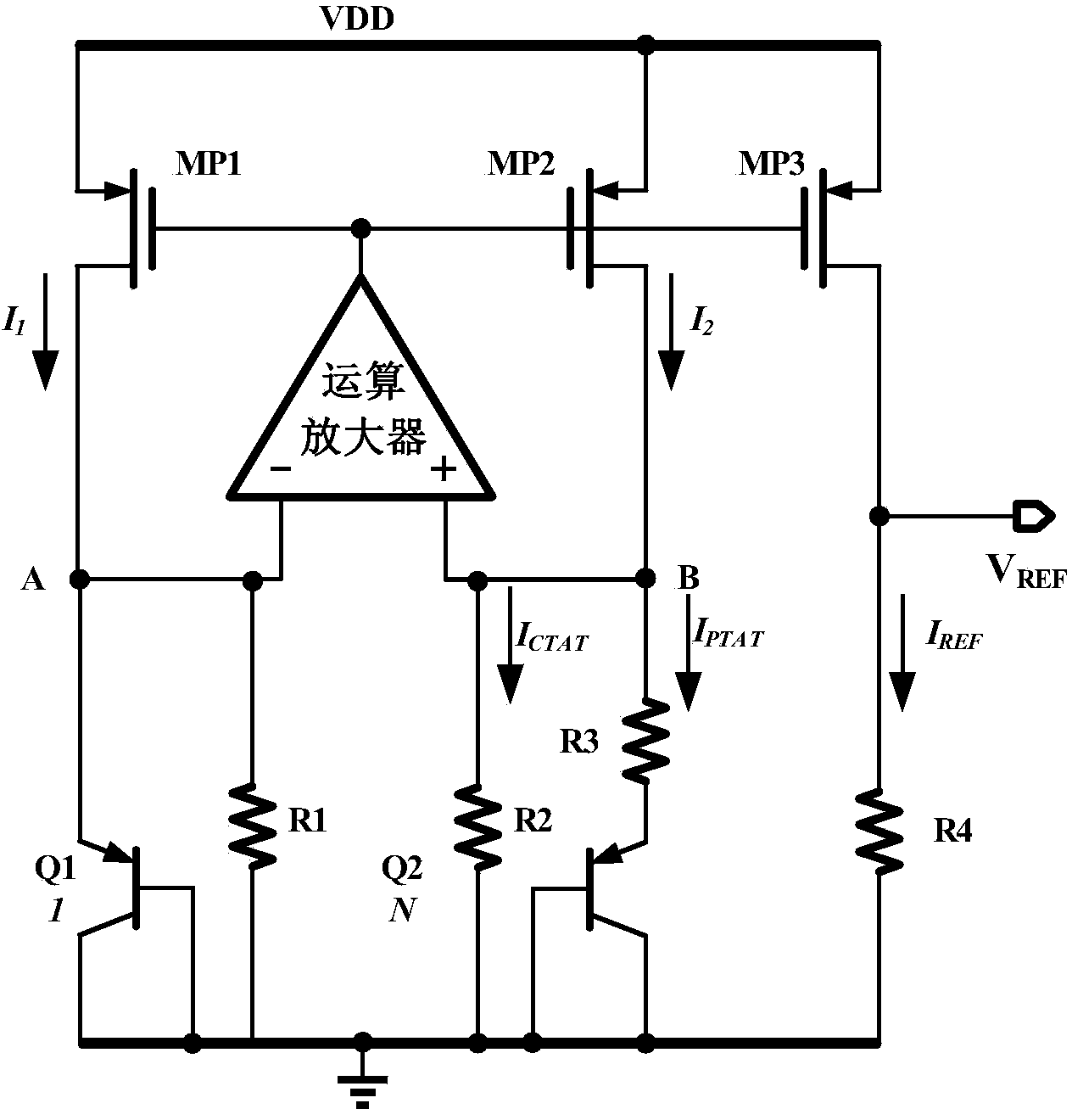
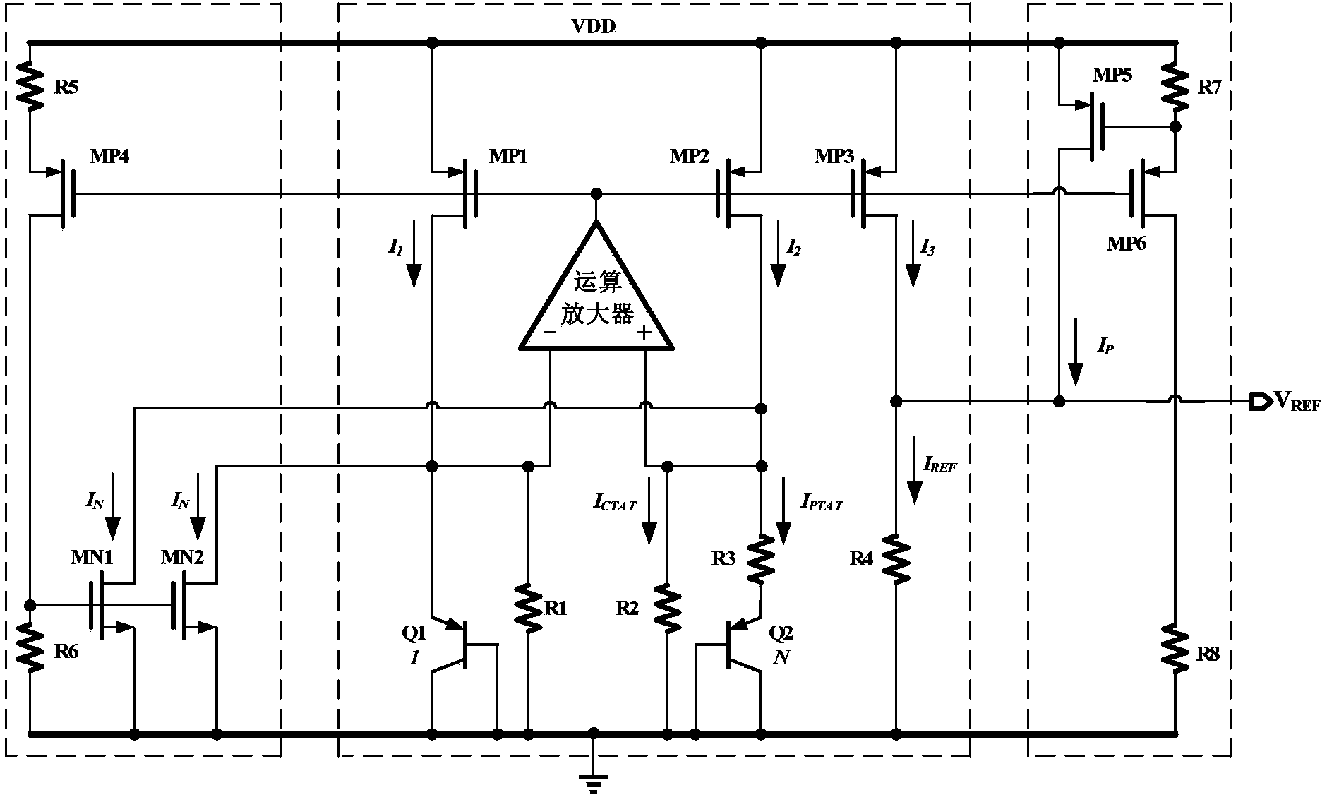
[0053] as attached image 3 As shown, the current mode bandgap reference structure of the subthreshold current compensation of the present invention includes a bandgap reference core circuit, a first MOS tube subthreshold current compensation circuit and a second MOS tube subthreshold current compensation circuit, and a bandgap reference core circuit and figure 2 The structure of the current mode bandgap reference circuit in the prior art is exactly the same. Including operational amplifier, PMOS tube MP1, PMOS tube MP2, PMOS tube MP3, PNP tube Q1, PNP tube Q2, resistor R1, resistor R2, resistor R3, resistor R4, the non-inverting input of the operational amplifier is connected to the drain of the PMOS tube MP2 , the inverting input terminal of the operational amplifier is connected to the drain of the PMOS transistor MP1, the gate of the PMOS transistor MP1, PMOS transistor MP2 is connected to the gate of the PMOS transistor MP3 and connected to the output terminal of the op...
PUM
 Abstract
Description
Claims
Application Information