MEMS capacitive switch

A capacitive switch and ground electrode technology, which is applied in the field of electronic science, can solve the problems of limiting the application range of RFMEMS switches, the influence of switch radio frequency performance, and the large up-state capacitance of switches, so as to alleviate insertion loss and drive voltage, improve isolation, increase The effect of large down-state capacitance

Inactive Publication Date: 2014-09-10
UNIV OF ELECTRONICS SCI & TECH OF CHINA
View PDF6 Cites 18 Cited by
  • Summary
  • Abstract
  • Description
  • Claims
  • Application Information

AI Technical Summary

Problems solved by technology

However, all the switch beams of this structure are placed on the same plane. If the distance between the switch beam and the transmission line is too small, the up-state capacitance of the switch will be large, resulting in an increase in the insertion loss of the switch. If the distance between the switch beam and the transmission line is increased Due to the square relationship between the driving voltage and the spacing, the driving voltage of the switch will increase sharply. In addition, the roughness of the dielectric layer has a greater impact on the RF performance of the switch, which will severely limit the RF performance of the switch. Applications of MEMS switches

Method used


Image

  • MEMS capacitive switch
  • MEMS capacitive switch
  • MEMS capacitive switch

Examples


Embodiment Construction

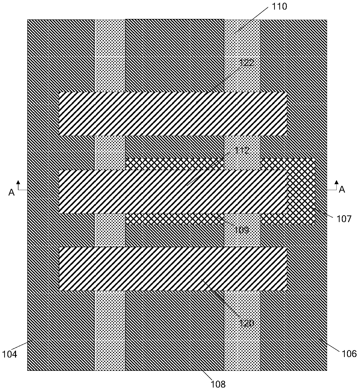
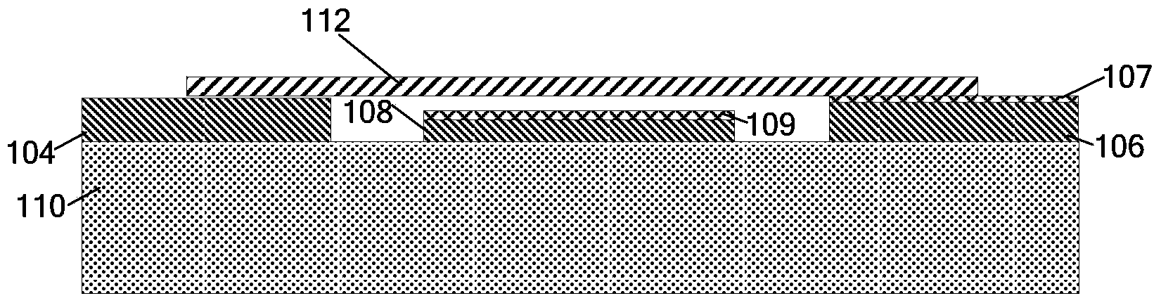
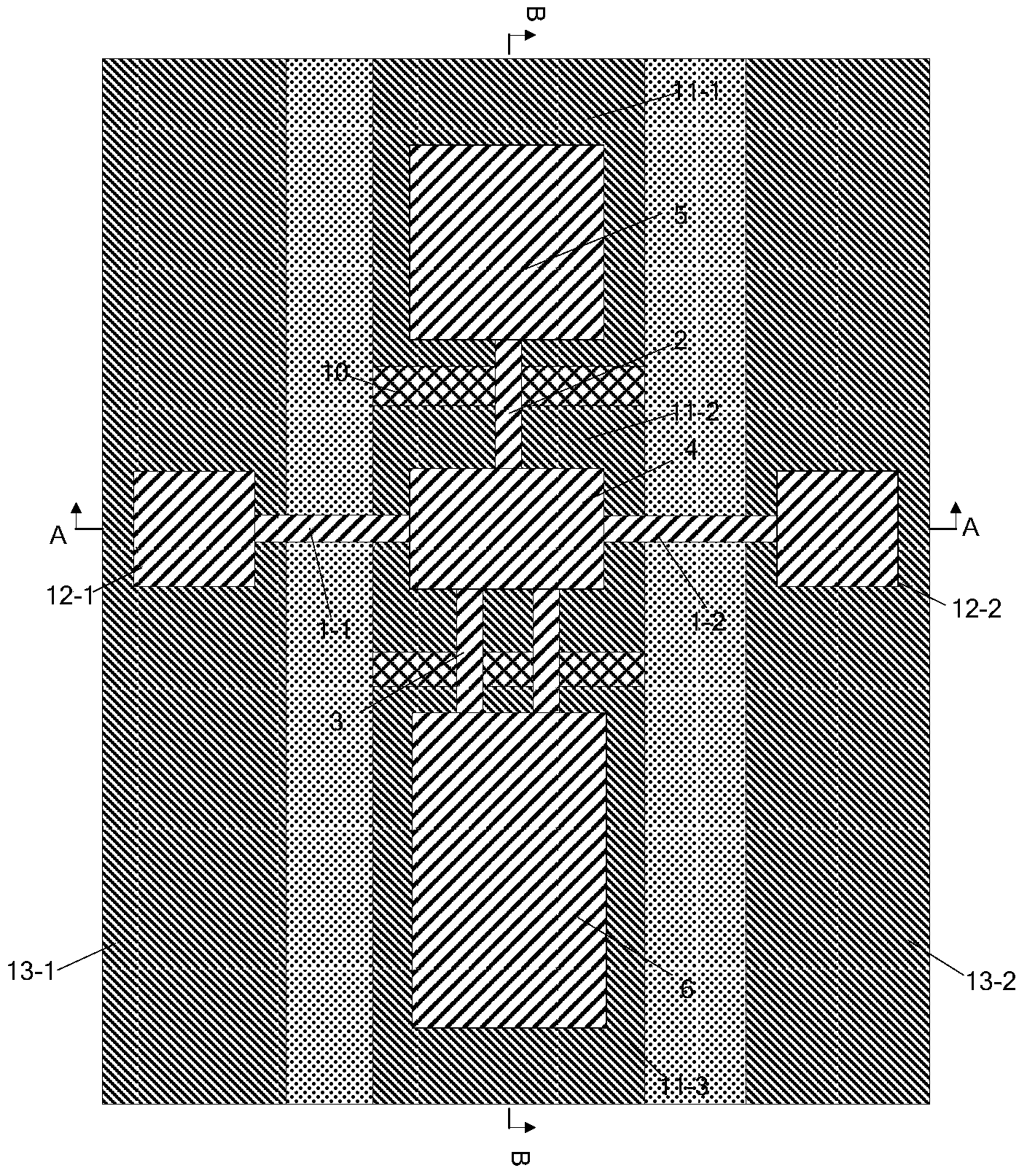
[0028] A MEMS capacitive switch, such as Figure 3 to Figure 5 As shown, it includes a substrate 7 with an insulating layer 8 on the surface, a signal transmission line 9 made of conductive material in the middle of the surface of the insulating layer 8, and a signal transmission line 9 parallel to the signal transmission line on the surface of the insulating layer 8 on both sides of the signal transmission line 9. The ground electrodes 13-1 and 13-2 of 9 are fully covered with a layer of dielectric layer 10 on the surface of the signal transmission line 9, and the surface of the dielectric layer 10 is provided with a first metal covering area 11-2 and a second metal covering area 11- 1 and the third metal covering region 11-3, wherein the first metal covering region 11-2 is located between the second metal covering region 11-1 and the third metal covering region 11-3; on the surface of the first ground electrode 13-1 A first fixed anchor point 12-1 is set, a second fixed anch...


PUM


Abstract

The invention belongs to the technical field of electronic science, and relates to an MEMS capacitive switch. The MEMS capacitive switch comprises a substrate with an insulation layer, a signal transmission line and ground electrodes on the two sides, a dielectric layer is arranged on the surface of the signal transmission line, three metal coverage areas are arranged on the surface of the dielectric layer, the two ground electrodes are respectively provided with a fixed anchor point, and the two fixed anchor points support a drive electrode structure. The drive electrode structure is of a two-wing type phase step structure, and comprises a first drive electrode in the middle, a second drive electrode and a third electrode, the second drive electrode and the third electrode are arranged on the two wings, the two sides of the first drive electrode are connected with the fixed anchor points through clamped beams, the second drive electrode and the third drive electrode are connected with the first drive electrode through cantilever beams, and the distance between the second drive electrode and the third drive electrode and the signal transmission line is larger than the distance between the first drive electrode and the signal transmission line. The areas of the three drive electrodes are increased in sequence. Three work frequency bands can be achieved, and the MEMS capacitive switch has the advantages of being low in insertion loss, high in isolation degree and low in drop-down voltage and can be applied to a radio-frequency or microwave communication system.

Description

technical field [0001] The invention belongs to the technical field of electronic science and relates to microelectromechanical systems (MEMS), in particular to a MEMS capacitance switch. technical background [0002] Switches are fundamental components in radio frequency (RF) and microwave communication systems, and radio frequency microelectromechanical (RF MEMS) switches have great application space at both the RF and microwave component and system levels. At the component level, radio frequency microelectromechanical (RF MEMS) switches can be used to construct voltage-controlled oscillators, filters (capacitive switches, inductors) and phase shifters, etc., which are indispensable components of modern radar and communication systems. Compared with traditional FET and PIN diode switches, radio frequency microelectromechanical (RF MEMS) switches have the characteristics of low DC power consumption, low insertion loss, high isolation, low intermodulation distortion, wide op...

Claims


Application Information

Patent Timeline
Patent Type & Authority Applications(China)
IPC IPC(8): H01H59/00
Inventor 鲍景富王秋苹邓迪杜亦佳
Owner UNIV OF ELECTRONICS SCI & TECH OF CHINA
Why Eureka
Try Eureka