
A Linear Positioning Method Based on Marked Magnetic Source with Fixed Magnetic Dipole Moment

A fixed magnetic dipole moment, linear positioning technology, used in positioning, radio wave measurement systems, measurement devices, etc., can solve problems such as increased cost, inconvenience, and increased volume, and achieve the effect of high-precision positioning

Inactive Publication Date: 2016-12-07
ZHEJIANG UNIV
View PDF4 Cites 0 Cited by
  • Summary
  • Abstract
  • Description
  • Claims
  • Application Information

AI Technical Summary

Problems solved by technology

Since the solution to the nonlinear inverse problem of the position of the magnetic source and the attitude parameters of the marker is mostly implemented by an iterative optimization method, which is largely affected by the initial value of the iteration, the direction of the iteration, the convergence speed, and the convergence time, the existing research starts from the software and hardware to improve the marker. The accuracy and speed of magnetic source positioning, including increasing the number of magnetic field measurement sensors used to measure the magnetic field excited by the marked magnetic source, to obtain a magnetic field distribution with greater information, however, the increase in the number of sensors increases the cost of the entire magnetic source positioning system , increased volume, inconvenient use, and larger measurement sample data bring a great burden to the back-end signal processing; in addition, simplified nonlinear inverse solution models are obtained through matrix and line algebraic operations, however, these simplified models The solution still requires at least five magnetic field measurement sensor sampling data

Method used


Image

  • A Linear Positioning Method Based on Marked Magnetic Source with Fixed Magnetic Dipole Moment
  • A Linear Positioning Method Based on Marked Magnetic Source with Fixed Magnetic Dipole Moment
  • A Linear Positioning Method Based on Marked Magnetic Source with Fixed Magnetic Dipole Moment

Examples


Embodiment Construction

[0020] The present invention will be described in further detail below in conjunction with the accompanying drawings and embodiments.

[0021] The steps of the inventive method are as follows:

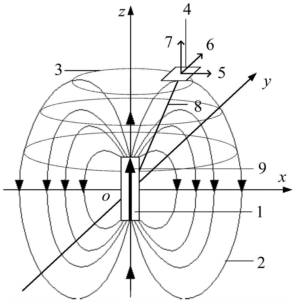
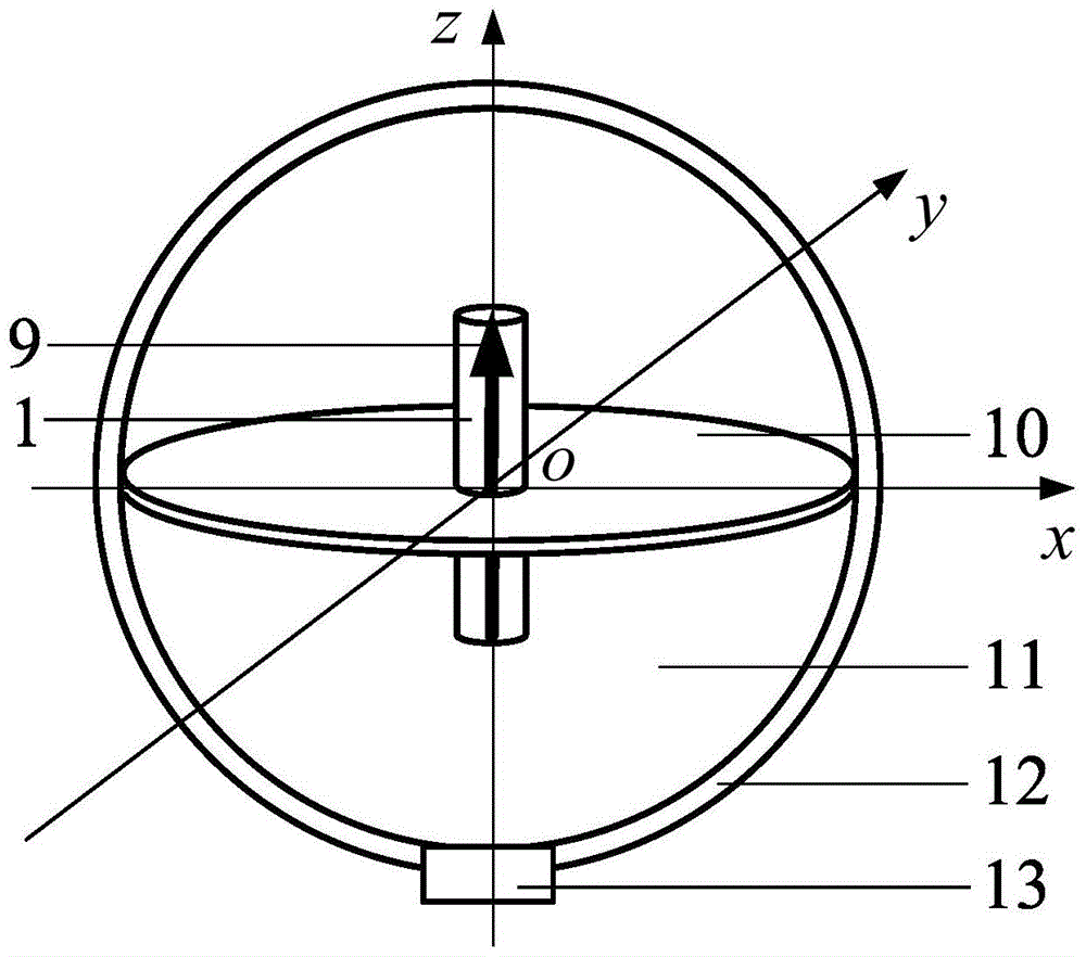
[0022] 1) Use the marked magnetic source to construct a spatial magnetic field, maintain a fixed spatial relative position between the marked object and the marked magnetic source, and the attitude of the marked magnetic source makes the marked magnetic source always have a vertical upward magnetic dipole through the attitude return mechanism moment, the marked object and the marked magnetic source are connected through the attitude return mechanism, and the corresponding relationship between the magnetic flux density distribution intensity of the magnetic field generated by the marked magnetic source at any measurement point in space and the distance between the measured point and the marked magnetic source is obtained;

[0023] 2) Establish an xyz rectangular coordinate system, the c...


PUM


Abstract

The invention discloses a linear positioning method based on a marked magnetic source with a permanent magnetic dipole moment. The linear positioning method based on the marked magnetic source with the permanent magnetic dipole moment comprises the steps that a space magnetic field is established by means of the marked magnetic source which has the vertically upward magnetic dipole moment all the time, and the corresponding relation between the magnetic flux density distribution intensity and the distances between measurement points and the marked magnetic source is obtained; an xyz rectangular coordinate system is established, and the magnetic flux density components, at the position of each measurement point in the space magnetic field, in all the directions of the coordinates are detected, so that the magnetic flux density distribution intensity and the distances between the measurement points and the marked magnetic source are obtained; all coordinate values at the position of the marked magnetic source are obtained according to the magnetic flux density components in all the directions of the coordinates and magnetic flux density components detected through a three-axis magnetic field measurement sensor based on a marked magnetic source magnetic coupling polaron positive model, and thus accurate positioning of a marked object is achieved. According to the linear positioning method based on the marked magnetic source with the permanent magnetic dipole moment, the solution to the location parameters of the magnetic source is achieved based on the linear model; compared with a traditional magnetic marking and positioning method, the linear positioning method has the advantages that only one three-axis magnetic sensor is needed, the solution can be achieved without the need of the non-linear iteration method, rapid positioning is achieved, the precision is high, and cost is low.

Description

technical field [0001] The invention relates to a magnetic marker positioning method, in particular to a linear positioning method based on a marker magnetic source with a fixed magnetic dipole moment. Background technique [0002] In the positioning technology based on magnetic markers, the spatial distribution of the magnetic field excited by the marker magnetic source and the position and attitude parameters of the marker magnetic source meet a specific physical model, and the magnetic measurement sensor is used to measure the distribution and spatial magnetic field excited by the marker magnetic source at the sampling position of the sensor. The physical model of the marked magnetic source is established to establish an objective function related to the position and attitude of the marked magnetic source, and the position and attitude parameters of the marked magnetic source to be solved are continuously adjusted through the nonlinear iterative inverse solution method to ...

Claims


Application Information

Patent Timeline
Patent Type & Authority Patents(China)
IPC IPC(8): G01S5/00
CPCG01S5/00
Inventor 付新申慧敏胡亮陈文昱
Owner ZHEJIANG UNIV
Learn More