A Low Dose CT Image Reconstruction Method

A CT image, low-dose technology, applied in image enhancement, image data processing, instruments, etc., can solve the problems of reducing the accuracy of reconstruction results, slow reconstruction speed, and a large number of interpolations, so as to achieve high-quality image reconstruction, avoid interpolation operations, The effect of improving accuracy

Inactive Publication Date: 2017-01-11
SHANGHAI INST OF APPLIED PHYSICS - CHINESE ACAD OF SCI
View PDF4 Cites 0 Cited by
  • Summary
  • Abstract
  • Description
  • Claims
  • Application Information

AI Technical Summary

Problems solved by technology

[0005] The most widely used traditional CT reconstruction method is filtered back projection (FBP). This method is easy to implement and fast in reconstruction speed. However, when the projection angle is incomplete, filtered back projection often cannot give satisfactory results.
At the same time, since the method uses an interpolation algorithm in the back-projection process, artifacts will inevitably appear in the reconstruction results, which will eventually lead to a decrease in image quality. More importantly, the FBP algorithm requires a large number of projection angles, which makes the sample in the data acquisition process Receive a large radiation dose, which will bring radiation damage to the examinee in medical CT applications
Other CT reconstruction algorithms, such as Algebraic Iterative Algorithm (ART) and Expectation Maximization Algorithm (EM), can effectively solve the problem of incomplete projection angles, and can use a small number of projections to achieve image reconstruction, effectively reducing the radiation dose to the sample , but its reconstruction process only involves the Cartesian coordinate system and the polar coordinate system, thus requiring a lot of interpolation, which reduces the accuracy of the reconstruction results, and at the same time, the reconstruction speed is slow, which limits its scope of application

Method used


Image

  • A Low Dose CT Image Reconstruction Method
  • A Low Dose CT Image Reconstruction Method
  • A Low Dose CT Image Reconstruction Method

Examples


example 1

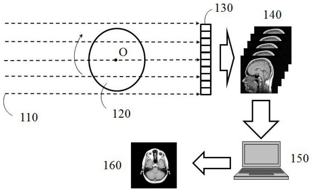
[0098] see Figures 5A-5D as shown, Figure 5A is the original image used for simulation reconstruction, Figure 5B is the sinogram obtained using parallel beam projection, Figure 5C and Figure 5D It is the reconstruction map obtained by using the present invention. The size of the original image and the reconstructed image is 512×512 pixels to simulate the image acquisition mode of the present invention in the parallel beam projection process, the starting angle is -45 degrees, and a total of 128 angles are acquired. In the process of image reconstruction, the boundary constraint condition used in time domain space is a fixed rectangular window of 376×408 pixels; further, in each iteration process, all pixel values ​​outside the boundary are set to zero, and the operation of pixel values ​​inside the boundary is: when The pixel value of the next iteration minus the product of the pixel value of the previous iteration and the adjustment coefficient is used as the input v...

example 2

[0101] see Figures 6A-6B as shown, Figure 6A is the reconstruction result obtained by conventional filtered back projection (FBP), Figure 6B is the reconstruction result obtained by using the image reconstruction method of the present invention. The experimental sample is a solidified concrete material. The projection data correction in step (2) includes normalization, phase restoration, zero padding and registration. The theoretical formula of phase restoration refers to T.E.Gureyev, T.J.Davis, A.Pogany, S.C.Mayo , S.W.Wilkins.Appl.Opt.43(12):2418-2430(2004) and T.E.Gureyev, A.Pogany, D.M.Paganin, S.W.Wilkins.Opt.Commun.231(1-6):53-70(2004) . The center of gravity method is used for registration, and its theoretical formula refers to Chien-Chun Chen, Jianwei Miao, and T.K.Lee.PhysRevB.79(5).052102(2009). The size of the reconstructed image is 1000×1000 pixels, the boundary constraints used in the time domain space in the process of image reconstruction are fixed rectan...

example 3

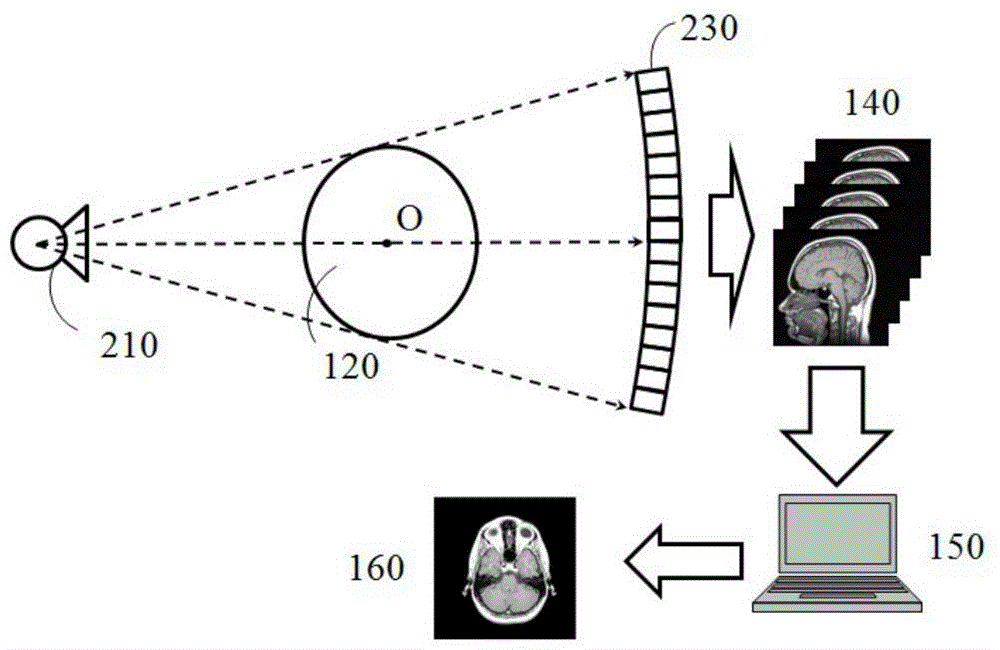
[0103] see Figures 7A-7C as shown, Figure 7A is the original image used for simulation reconstruction, Figure 7B is the sinogram obtained by fan beam projection, Figure 7C It is the reconstruction map obtained by using the present invention. The size of the original image and the reconstructed image is 512×512 pixels, which is used to simulate the reconstruction of the data projected by the fan beam radiation source. The starting angle is -45 degrees, and a total of 128 angles are obtained. The rotation center is the geometry of the original image. center. Step (1) includes converting the fan beam projection into a parallel beam projection using a rearrangement algorithm. The theoretical formula of the rearrangement algorithm is referenced in Guy Besson.Medical Physics 26(3):415-426 (1998). In the process of image reconstruction, the boundary constraint condition used in time domain space is a fixed rectangular window of 371 × 450 pixels, the adjustment coefficient is ...


PUM


Abstract

The invention provides a low-dose CT image reconstruction method. The low-dose CT image reconstruction method comprises the following steps that (1) projection data of equal-slope increments with different projection angles theta are obtained; (2) the projection data are corrected; (3) Fourier transform is conducted on the corrected projection data so that the corrected projection data can be converted into frequency domain spatial data in a polar coordinate system; (4) the frequency domain spatial data in the polar coordinate system are converted into frequency domain spatial data in a pseudo-polar coordinate system; (5) repeated conversion between the frequency domain space in the pseudo-polar coordinate system and the time domain space in a Cartesian coordinate system is conducted on the frequency domain spatial data obtained in the step (4) through the iteration method until the preset final condition is met; (6) a time domain image meeting the final condition is output. By the adoption of the low-dose CT image reconstruction method, the quality of a reconstructed image is guaranteed, and the radiation dose borne by a sample can be effectively reduced.

Description

technical field [0001] The invention relates to an image reconstruction method, in particular to a low-dose CT image reconstruction method. Background technique [0002] Computed tomography (Computer Tomography, CT) is an effective non-destructive three-dimensional detection technology, which can solve the tomographic slice from the two-dimensional projection of the sample and realize three-dimensional visualization. Scientific fields such as biology, as well as industrial non-destructive testing, play an important role. see figure 1 and 2 , a typical CT imaging system includes radiation sources (parallel beam 110, fan beam 210, and cone beam) and detectors (planar detector 130 and non-planar detector 230) with certain penetrating capabilities, and a sample stage between them 120, through the relative rotation (rotation center O) between the sample, the radiation line and the detector, the projection images of the sample at different angles are obtained 140, and then the ...

Claims


Application Information

Patent Timeline
Patent Type & Authority Patents(China)
IPC IPC(8): G06T5/00
Inventor 周光照杜国浩佟亚军陈荣昌任玉琦王玉丹谢红兰邓彪肖体乔
Owner SHANGHAI INST OF APPLIED PHYSICS - CHINESE ACAD OF SCI
Why Eureka
Try Eureka