Steel plate surface treatment method and device

A surface treatment device and surface treatment technology, applied in the direction of workpiece surface treatment equipment, workpiece cleaning device, metal rolling, etc., can solve the problems of failure to meet requirements, inability to flexibly control roughness, and decrease of roll surface roughness, and achieve reduction Effect of load and its equipment section length, control of strip surface roughness, and improvement of strip mechanical properties

Active Publication Date: 2014-09-24
BAOSHAN IRON & STEEL CO LTD
View PDF9 Cites 27 Cited by
  • Summary
  • Abstract
  • Description
  • Claims
  • Application Information

AI Technical Summary

Problems solved by technology

In the initial stage of the work roll, the surface roughness of the roll is the key factor to determine the surface roughness of the strip, but with the increase of the rolling mileage, the surface roughness of the roll decreases, so that the surface roughness of the strip cannot meet the user's requirements;
[0010] 2) The only way to control the roughness of the strip during the leveling process is to control the roughness of the roll. In actual production, when the roughness of the finished product is found to be unsatisfactory, the roll can only be replaced, and the roughness cannot be flexibly controlled during production;
[0011] 3) As the demand for high-strength steel increases, the strength of the strip steel is also getting higher and higher. When the strength of the strip steel reaches a certain level, it is no longer possible to achieve the roughness value required by the user through the tempering machine, even in the work roll Unable to meet the requirements when it was first launched
The medium used to impact the surface of the steel strip in this invention is dry solid particles, which will cause the metal plate entering the projection chamber to be dry in order to maintain the fluidity of the solid particles. Therefore, it is necessary to have a steel plate on the projection chamber Washing and drying equipment, resulting in complicated unit
Moreover, no liquid can enter the unit during the entire projection and cleaning process, which puts high demands on the sealing of the equipment, which is difficult to achieve in actual production.
In addition, the solid particles are directly impacted on the surface of the metal plate, because the particle size of the solid particles is larger than that of the metal plate, so the metal particles are easy to embed on the surface of the metal plate, which cannot be achieved by the air injection method in this invention. The purpose of completely removing solid particles on the surface of the strip steel

Method used


Image

  • Steel plate surface treatment method and device
  • Steel plate surface treatment method and device
  • Steel plate surface treatment method and device

Examples


specific Embodiment approach

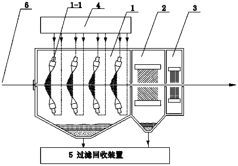
[0103] Take the technology when the strip surface treatment device described in the present invention is set on the independent degreasing unit as an example, refer to image 3 , the specific implementation is as follows:

[0104] The steel strip in this embodiment is a cold-rolled steel strip with a width of 700-1300 mm and a thickness of 0.2-3 mm. At this time, various dirt generated during the rolling process remains on the surface of the strip, including rolling oil and slag in the rolling oil, iron powder generated during the cold rolling process, accumulated dust, and dust generated during the welding process. Welding slag etc. The surface roughness of the strip after cold rolling is 0.7-0.8 μm, and the user requires a surface roughness of 1.5 μm.

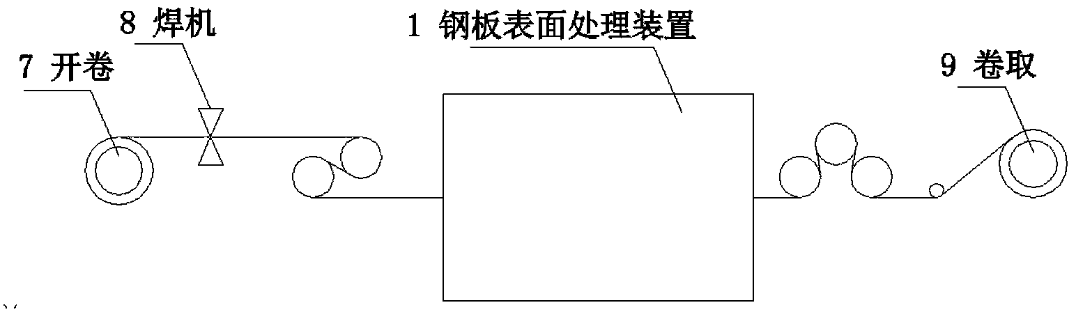
[0105] The steel strip 6 is welded by the welding machine 8 after being decoiled by the uncoiler 7, and then enters the steel plate surface treatment device 1 through the tension roller, and the steel plate pretreatment dev...

Embodiment 2

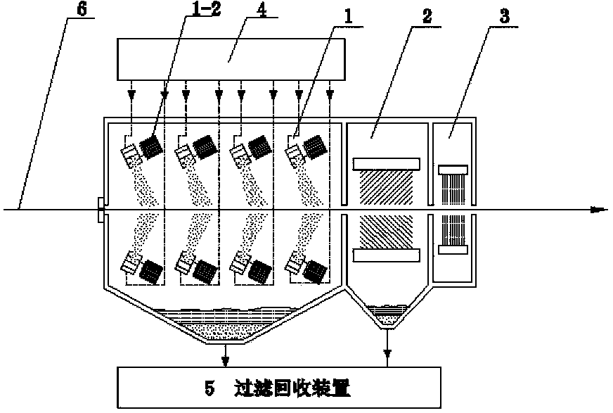
[0108] Take the process when the strip surface treatment device described in the present invention is set on the continuous annealing unit as an example, refer to Figure 4 , the specific implementation is as follows:

[0109] The steel strip in this embodiment is a cold-rolled steel strip with a width of 700-1300 mm and a thickness of 0.2-3 mm. At this time, various dirt generated during the rolling process remains on the surface of the strip, including rolling oil and slag in the rolling oil, iron powder generated during the cold rolling process, accumulated dust, and dust generated during the welding process. Welding slag etc. The surface roughness of the strip after cold rolling is 0.7-0.8 μm, and the user requires a surface roughness of 1.5 μm.

[0110]The steel strip 6 is welded by the welder 8 after being decoiled by the uncoiler 7, and then enters the steel plate surface treatment device 1. The technology in the steel plate surface treatment device is the same as tha...

Embodiment 3

[0112] Take the process when the strip surface treatment device described in the present invention is set on the continuous hot-dip galvanizing unit as an example, refer to Figure 5 , the specific implementation is as follows:

[0113] After the steel strip 6 is uncoiled by the uncoiler 7, it enters the inlet looper 10 through the welding machine 8, and then enters the steel plate surface treatment device 1. The strip steel surface treatment process in the steel plate pretreatment device 1 is similar to that of Example 1. After the steel strip processed by the pretreatment device 1 is annealed in the annealing furnace 12, it is then subjected to hot-dip galvanizing treatment, thereby completing the entire hot-dip galvanizing process.


PUM

PropertyMeasurementUnit
particle sizeaaaaaaaaaa
surface roughnessaaaaaaaaaa
widthaaaaaaaaaa

Abstract

An apparatus for treating a surface of a steal plate, sequentially comprising: a strip steel surface treatment unit (1) provided with a high-pressure ejection device (1-1) or a centrifugal throwing device (1-2), a strip steel surface cleaning unit (2), and a strip steel surface drying unit (3), one or both of the high-pressure ejection device and the centrifugal throwing device being arranged, and slurry, namely a mixture of solid abrasive and water, being sprayed onto the surface of the strip steel; and further comprising a slurry supply unit (4) and an abrasive filtering and recovery unit (5). Also disclosed is a method for treating a surface of a steal plate. In the treatment method, by spraying the solid mixed abrasive onto the surface of the strip steel, the surface roughness of the strip steel is controlled, and further, the oil, iron oxide scales and some dirty things on the surface of the strip steel can be cleared, thereby fully or partially replacing the smoothing process function.

Description

technical field [0001] The invention belongs to the technical field of post-processing line for steel plates after cold rolling, in particular, the invention relates to a steel plate surface treatment method and its device. Impact a mixture of water and solid particles in a certain proportion on the surface of the strip steel. On the one hand, it can give a certain roughness to the surface of the strip steel, and at the same time remove the grease, iron oxide scale and some dirt on the surface of the strip steel. In addition, by impacting the surface of the strip steel The method of modulating the mechanical properties of strip steel completely or partially replaces the function of the leveling process. Background technique [0002] After the steel strip is rolled to a certain thickness by the cold rolling mill, it needs to enter different post-processing processes according to the product requirements. For example, hot-dip galvanized products need to enter the continuous ga...

Claims


Application Information

Patent Timeline
Patent Type & Authority Applications(China)
IPC IPC(8): B21B45/00B21B45/02
CPCB21B45/0269B21B45/08B21B45/02B21B45/0287B21B45/0284B24C1/00
Inventor 全基哲李山青段明南王英杰徐江华瞿培磊
Owner BAOSHAN IRON & STEEL CO LTD
Why Eureka
Try Eureka