Internal thread tapper and tapping method thereof

A tapping device and internal thread technology, applied in the field of thread processing, can solve the problems of inability to drive the processing of tap products, low motor power of desktop drilling machines, and inability to meet mass production, so as to shorten loading and unloading time, reduce labor intensity and loss of tools , the effect of simple structure

Active Publication Date: 2014-09-24
HUNAN NANFANG AVIATION HIGH ACCURATE DRIVE
View PDF5 Cites 5 Cited by
  • Summary
  • Abstract
  • Description
  • Claims
  • Application Information

AI Technical Summary

Problems solved by technology

[0002] Tapping is the most widely used internal thread processing method. For the processing method of small and medium-sized internal threads (below M8), the main method is to install a drill chuck on a bench drill machine to hold a tap on a small tapping machine. A tapping method, for quenched materials with high hardness requirements (such as HRC25-35), because the cutting force is relatively large, while the motor power of the desktop drilling machine is relatively small, and the spindle rotation speed is high, the tap is prone to stop during the tapping process. As a result, it is impossible to drive the tap for product processing
For the processing of internal threads between M8 and M24, ordinary lathes are mainly used for threading. This processing method has slow tapping speed, long processing cycle, low processing efficiency and high production cost, which cannot meet the requirements of mass production.
When tapping with an elastic clamping sleeve, the machine tap is easy to loosen, and because the machine tap is brittle, it is easy to break the teeth during the tapping process, resulting in unstable product quality

Method used


Image

  • Internal thread tapper and tapping method thereof
  • Internal thread tapper and tapping method thereof

Examples


Embodiment Construction

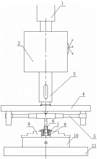
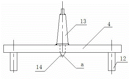
[0025] The internal thread tapping device of the present invention includes a vertical drilling machine, a three-jaw chuck 10 , a guiding push rod 4 , a tap hinge rod 5 and a tap 6 . A Morse taper pin 13 is provided in the middle of the guide push rod 4 , and cylindrical retaining pins 12 are provided at both ends. The lower end of the Morse taper pin 13 is provided with a cylindrical taper pin 14, and the taper angle a of the cylindrical taper pin 14 is 60 degrees. The Morse taper pin 13 and the cylindrical stop pin 12 are connected with the guide push rod 4 by welding. The Morse taper pin 13 on the guiding push rod 4 is connected with the main shaft 3 of the vertical drilling machine.

[0026] Internal thread tapping device of the present invention taps like this:

[0027] A. According to the size specification of the internal thread of the part 7, select the guide push rod 4 that matches the tap hinge rod 5;

[0028] B. Insert the mounting end of the Morse taper pin 13 o...


PUM


Abstract

The invention relates to an internal thread tapper and a tapping method thereof. The internal thread tapper comprises a vertical driller, a three-jaw chuck, a guide push rod, a screw tap toggle and a screw tap. The internal thread tapper has the key points that the middle of the guide push rod is provided with a Morse cone pin, and both ends of the guide push rod are respectively provided with a cylindrical stop pin; the lower end of the Morse cone pin is provided with a cylindrical taper pin; the Morse cone pin and the cylindrical stop pin are fixedly connected with the guide push rod; a part is arranged on the three-jaw chuck; the guide push rod and the screw tap are driven to rotate in sequence by the main shaft of the vertical driller to perform tapping on the part. The tapper disclosed by the invention is simple in structure, easy to manufacture and low in cost; the screw tap is guided by adopting the guide push rod to perform internal thread tapping on the part on the vertical driller; the part is convenient to assemble and disassemble, the process is simple, the operation is easy, and the positioning accuracy is high, so that the assembly and disassembly time of the part is shortened, the labor strength of a worker and the tool loss are reduced, the production efficiency is improved, the production cost is reduced, and the processed part is stable in quality and high in reliability.

Description

technical field [0001] The invention relates to a thread processing method, in particular to an internal thread tapping device and a tapping method thereof. Background technique [0002] Tapping is the most widely used internal thread processing method. For the processing method of small and medium-sized internal threads (below M8), the main method is to install a drill chuck on a bench drill machine to hold a tap on a small tapping machine. A tapping method, for quenched materials with high hardness requirements (such as HRC25-35), because the cutting force is relatively large, while the motor power of the desktop drilling machine is relatively small, and the spindle rotation speed is high, the tap is prone to stop during the tapping process. Cause cannot drive screw tap to carry out product processing. For the processing of internal threads between M8 and M24, ordinary lathes are mainly used for threading. This processing method has slow tapping speed, long processing cyc...

Claims


Application Information

Patent Timeline
Patent Type & Authority Applications(China)
IPC IPC(8): B23G3/00
Inventor 叶丽红李石顺李洲朱美玲
Owner HUNAN NANFANG AVIATION HIGH ACCURATE DRIVE
Why Eureka
Try Eureka