Printing and dyeing wastewater afterheat recovery device

A waste heat recovery device, printing and dyeing sewage technology, applied in the direction of heating devices, water heaters, fluid heaters, etc., can solve the problems of energy saving and emission reduction, cost reduction, heat energy loss of printing and dyeing sewage, hindering development momentum, etc., and achieve improvement Production working environment, reducing human resource input, improving production efficiency and product quality

Inactive Publication Date: 2014-09-24
刘猛 +1
View PDF7 Cites 1 Cited by
  • Summary
  • Abstract
  • Description
  • Claims
  • Application Information

AI Technical Summary

Problems solved by technology

[0002] The production and sales of my country's printing and dyeing industry maintain continuous growth. While maintaining a certain growth rate and expanding scale, the printing and dyeing industry also pays more attention to technological progress, technological innovation and improvement of management level, actively responds to the pressure of rising production cost technology, and improves the profitability of enterprises and level, improve the quality and efficiency of economic growth, but due to energy consumption and environmental pollution in the printing and dyeing industry, the development momentum of the industry has been hindered objectively. Thus restricting the development of many printing and dyeing enterprises
[0003] The heating of printing and dyeing water in the printing and dyeing work is a major factor of energy consumption. At present, the conventional practice of sewage in the printing and dyeing industry is to discharge the printing and dyeing sewage directly from the underground ditch of each workshop to the centralized pool. The temperature of the printing and dyeing sewage is generally 50 ℃ - 60°C, then cooled to 35°C-30°C through the cooling tower, and then sent to the biological treatment tank for purification treatment. Generally, the pH value is about 8-11. The printing and dyeing sewage discharged in this way is highly corrosive, and the temperature is high. It is also very large, generally 300-3000 tons per day. During the discharge process, the heat energy in the heated printing and dyeing sewage is lost in vain, and it also consumes the energy consumed during the operation of the cooling tower, so it is impossible to achieve energy saving and emission reduction. purpose of cost reduction

Method used


Image

  • Printing and dyeing wastewater afterheat recovery device
  • Printing and dyeing wastewater afterheat recovery device
  • Printing and dyeing wastewater afterheat recovery device

Examples


Embodiment 1

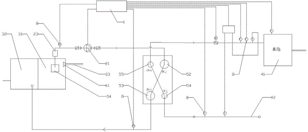
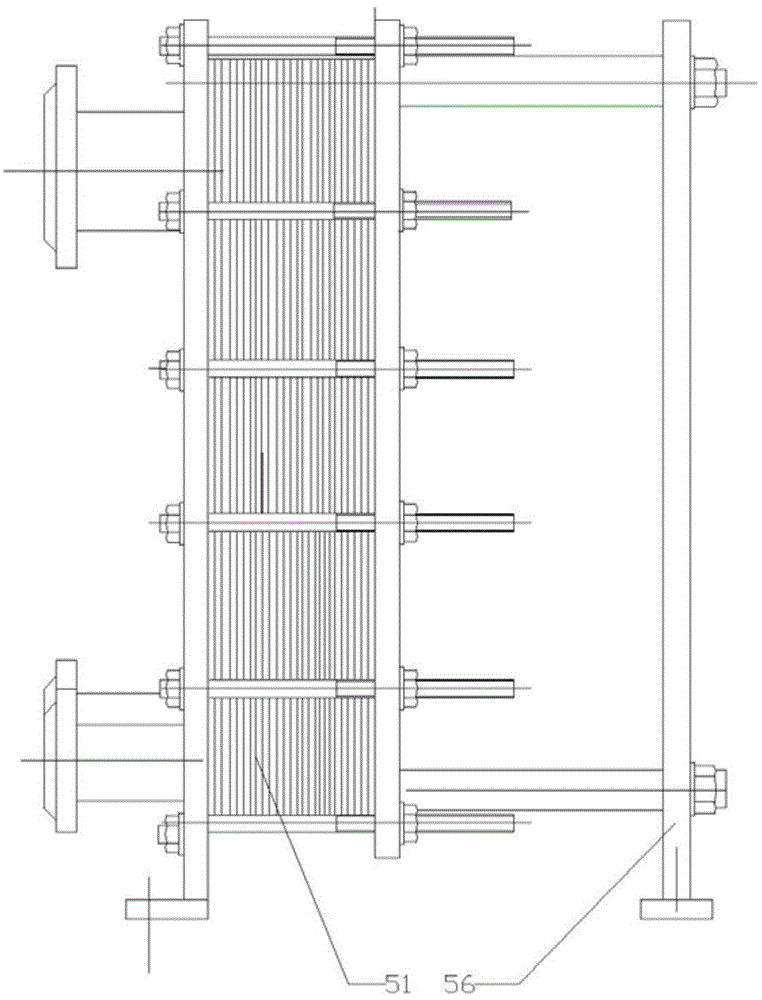
[0022] like figure 1 , image 3 , Figure 4 , Figure 5 As shown, in this embodiment, the waste heat recovery device for printing and dyeing sewage includes a sewage tank, a water pump I21, and an on-site control cabinet 1. The water pump I21 is electrically connected to the on-site control cabinet 1, and is provided by the water pump I21. The power of sewage circulating in the hot water channel. The sewage pool includes a heat recovery front pool 31 and a heat recovery rear pool 32. The heat recovery front pool 31 is used as a high-temperature sewage container for storing high-temperature sewage directly discharged by printing and dyeing equipment , to prepare for the next step of heat exchange recovery, the heat recovery rear pool 32 is used as a container for the sewage after heat exchange recovery, the heat recovery front pool 31 is provided with a sewage water inlet 33, and the heat recovery front pool 31 The position of the sewage water inlet 33 is provided with a wat...

Embodiment 2

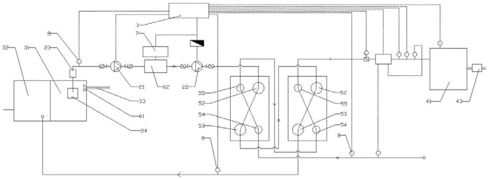
[0026] like figure 2 As shown, in this embodiment, the present invention includes two interconnected waste heat recoverers, the sewage heat exchange flow channel of the former waste heat recovery device is connected with the sewage heat exchange flow channel of the latter waste heat recovery device, and the former waste heat recovery device The clean water heat exchange channel of the waste heat recovery device is connected with the clean water heat exchange channel of the next waste heat recovery device. temperature for secondary heat exchange to recover heat, so as to achieve a more sufficient effect of heat exchange; the waste heat recovery device can be selected according to actual requirements during implementation, it can be one, or two or more connected, generally Two are preferred in the situation, which can not only effectively control the cost and process difficulty, but also fully recover the heat of sewage for heat exchange. In this example, the temperature of cle...


PUM


Abstract

The invention discloses a printing and dyeing wastewater afterheat recovery device, and aims to provide a printing and dyeing wastewater afterheat recovery device capable of recovering heat energy, saving energy, reducing emissions and effectively improving a production environment. The device comprises a wastewater tank, a water pump I and a field control cabinet, wherein the wastewater tank comprises a front heat recovery tank and a rear heat recovery tank; the front heat recovery tank is provided with a wastewater inlet. The device also comprises a clean water tank, a clean water supply pipe and one or more mutually connected afterheat recovery devices, wherein each afterheat recovery device comprises a wastewater heat exchange flow passage and a clean water heat exchange flow passage; a plurality of heat exchange plates are arranged outside each of the wastewater heat exchange flow passages and the clean water heat exchange flow passages; the front heat recovery tank, the water pump I, the wastewater heat exchange flow passages and the rear heat recovery tank are sequentially communicated through a pipeline; the clean water supply pipe, the clean water heat exchange flow passages and the clean water tank are sequentially communicated through a pipeline. The device can be widely applied to the field of printing and dyeing wastewater afterheat recovery.

Description

technical field [0001] The invention relates to a heat recovery device, in particular to a waste heat recovery device for printing and dyeing sewage. Background technique [0002] The production and sales of my country's printing and dyeing industry maintain continuous growth. While maintaining a certain growth rate and expanding scale, the printing and dyeing industry also pays more attention to technological progress, technological innovation and improvement of management level, actively responds to the pressure of rising production cost technology, and improves the profitability of enterprises and level, improve the quality and efficiency of economic growth, but due to energy consumption and environmental pollution in the printing and dyeing industry, the development momentum of the industry has been hindered objectively. Thus restricting the development of many printing and dyeing enterprises. [0003] The heating of printing and dyeing water in the printing and dyeing wo...

Claims


Application Information

Patent Timeline
Patent Type & Authority Applications(China)
IPC IPC(8): F24J3/00F24H1/00
Inventor 刘猛刘凤林
Owner 刘猛
Why Eureka
Try Eureka