Handheld firework mounting machine

A technology of mounting machine and mounting mechanism, which is applied in the direction of weapon types, pyrotechnics, offensive equipment, etc., can solve the problems of difficult product quality assurance, labor and time consumption, low production efficiency, etc., and achieve the goal of reducing production process and production time Effect

Inactive Publication Date: 2014-09-24
刘宗献
View PDF8 Cites 4 Cited by
  • Summary
  • Abstract
  • Description
  • Claims
  • Application Information

AI Technical Summary

Problems solved by technology

[0002] In the prior art, the production processes of filling mud, filling propellants, covering paper and installing effect bodies in the production of hand-held fireworks fireworks are all completed by production workers in a manual way. The production efficiency is low and the product quality is low. Difficult to guarantee, especially in the process of installing the cardboard, the cardboard must first be stamped into a single cardboard, and then the formed cardboard monomers are put into the paper tube one by one and installed separately. The installation time is long, and sometimes the installation is not in place. , so it takes a lot of labor and time, and at the same time, the safety of hand-made production is low, and the charge of medicine and dust is large, which is very harmful to the workers' health, and may even cause casualties.
This low-energy-efficiency production technology has been unable to meet the needs of the development of the fireworks market and the requirements of standardized fireworks production. In order to improve the production efficiency of fireworks production and installation, ensure safe production, and improve product quality, the inventor has developed a substitute for manual installation by workers. Hand-held fireworks installation machines and auxiliary equipment or molds / accessories, currently there is no handheld fireworks installation machinery and equipment on the market

Method used


Image

  • Handheld firework mounting machine
  • Handheld firework mounting machine
  • Handheld firework mounting machine

Examples


Embodiment Construction

[0039] Below, the present invention will be described in more detail with reference to the drawings and specific embodiments.

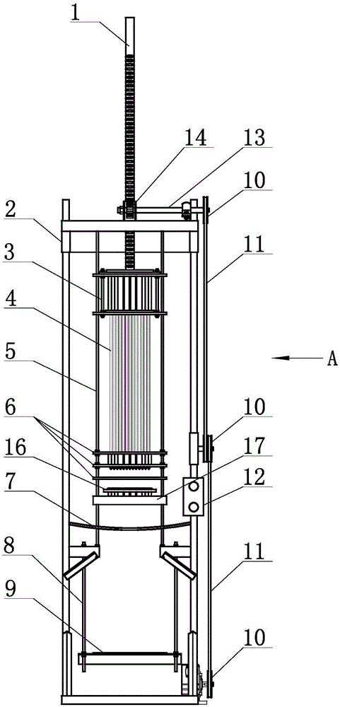
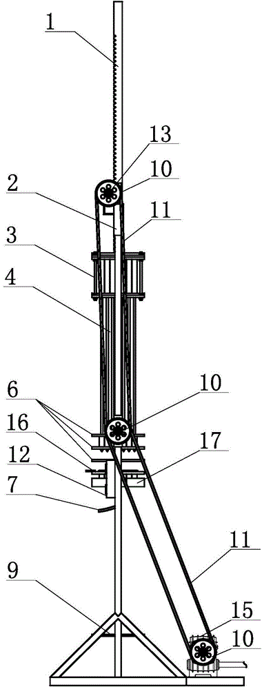
[0040] figure 1 , figure 2 , image 3 , Figure 4 , Figure 5 , Image 6 , Figure 7 , Figure 8 , Figure 9 , Figure 10 , Figure 11 , Figure 12 , Figure 13 , Figure 14 , Figure 15 , Figure 16 , Figure 17 , Figure 18 , Figure 19 A preferred embodiment of the invention is shown. Its composition consists of lifting shaft 1, frame 2, drill rod control assembly 3, drill rod assembly 4, support connecting rod 5, drill rod guide plate assembly 6, combined cylinder fixing belt 7, load plate connecting rod 8, load bearing Plate 9, pulley 10, belt 11, control box 12, transmission shaft 13, drive gear 14, reducer 15, shaped brazing plate 16, shaped plate 17, combined cylinder 18, mud filling mold 19, propellant filling mold 20 , Effect body installation mold 21, paper bar combination plate 22, paper bar 23, drill rod length control...


PUM


Abstract

The invention discloses a handheld firework mounting machine, which comprises a frame, a lifting shaft rod which is inserted into the center of the top of the frame, two support connecting pull rods which are fixed on both sides in the frame and are connected vertically, a transmission mechanism which is positioned on one side of the frame and is connected with a driving power structure, and a combined barrel which is arranged in the center of the lower part of the inner side of the frame. The handheld firework mounting machine is characterized in that the two support connecting pull rods in the center segment of the upper part of the inner side of the frame are provided with a mounting structure which is connected with the lifting shaft rod; a carrying plate for carrying the combined barrel is arranged below a corresponding mounting mechanism; a shaping plate is arranged on the lower-middle parts of the two support connecting pull rods respectively; the shaping plates can be used for shaping and fixing the combined barrel below the shaping plates in cooperation with a shaping brazing plate; a combined barrel fixing belt is arranged below each shaping plate; a plurality of mounting accessories are connected with the lower ends of the combined barrel and the mounting mechanisms in sequence in a matching way. The handheld firework mounting machine has the advantages of simple design structure, convenience in operation and use, high production efficiency, reliable product mounting quality, high mechanical running stability, and the like.

Description

technical field [0001] The invention relates to equipment for producing and processing fireworks and firecrackers, in particular to a hand-held fireworks installation machine. Background technique [0002] In the prior art, the production processes of filling mud, filling propellants, covering paper and installing effect bodies in the production of hand-held fireworks fireworks are all completed by production workers in a manual way. The production efficiency is low and the product quality is low. Difficult to guarantee, especially in the process of installing the cardboard, the cardboard must first be stamped into a single cardboard, and then the formed cardboard monomers are put into the paper tube one by one and installed separately. The installation time is long, and sometimes the installation is not in place. , It needs to consume a lot of labor and time like this, and at the same time, the safety of hand-made production is low, and the filling of medicine and mud and d...

Claims


Application Information

Patent Timeline
Patent Type & Authority Applications(China)
IPC IPC(8): F42B4/30
Inventor 刘宗献
Owner 刘宗献
Why Eureka
Try Eureka