
Inductor substrate isolation structure of integrated circuit

A technology of integrated circuits and isolation structures, applied in circuits, electrical components, electrical solid devices, etc., can solve the problem that the eddy current effect of inductance on the substrate cannot be effectively eliminated, affect the quality factor and operating frequency of the inductance, and the loss of the inductance on the substrate major issues

Active Publication Date: 2014-09-24
ZHUHAI JIELI TECH
View PDF6 Cites 6 Cited by
  • Summary
  • Abstract
  • Description
  • Claims
  • Application Information

AI Technical Summary

Problems solved by technology

[0004] The defects in the prior art are: the eddy current effect of the inductance on the substrate cannot be effectively eliminated, resulting in excessive loss of the inductance on the substrate, affecting the quality factor of the inductance and the operating frequency

Method used


Image

  • Inductor substrate isolation structure of integrated circuit
  • Inductor substrate isolation structure of integrated circuit
  • Inductor substrate isolation structure of integrated circuit

Examples


Embodiment Construction

[0020] The present invention will be described in further detail below in conjunction with the embodiments and accompanying drawings, but the embodiments of the present invention are not limited thereto.

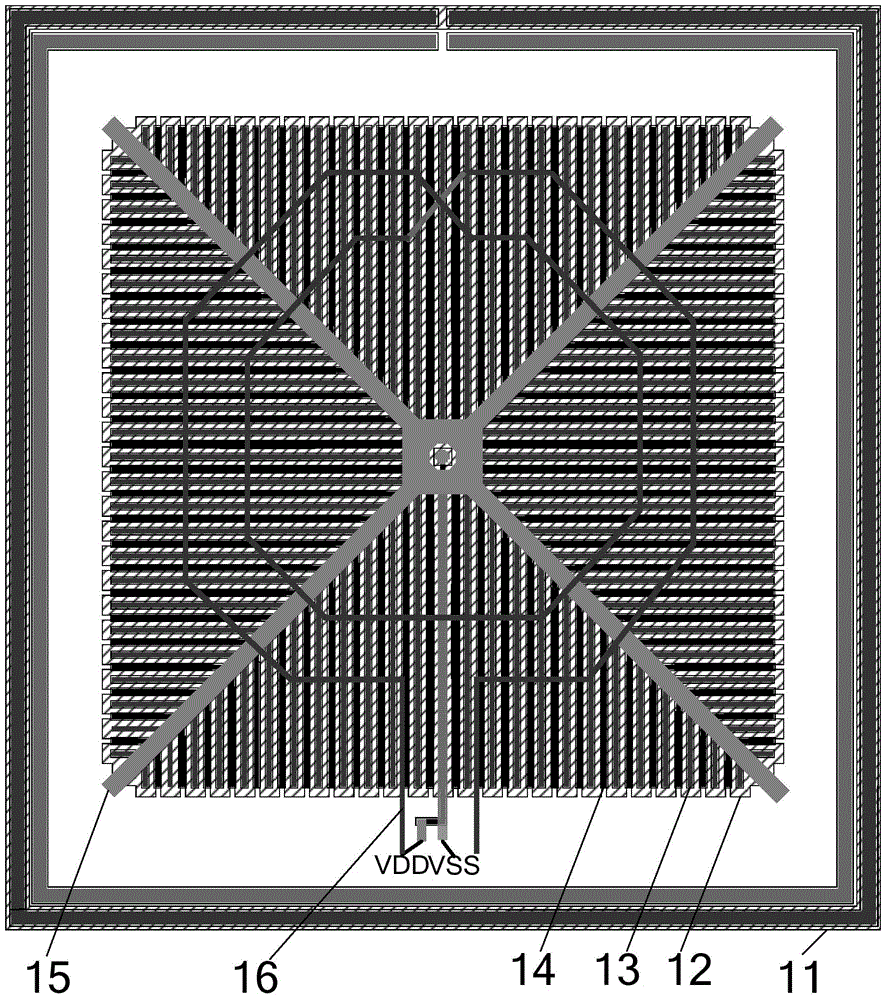
[0021] Such as figure 1 As shown, it is a structural schematic diagram of an inductive substrate isolation structure of an integrated circuit of the present invention in an embodiment, including:

[0022] p-type substrate 11;

[0023] An n-type well region formed in the p-type substrate 11, the n-type well region comprising a plurality of n-wells 12;

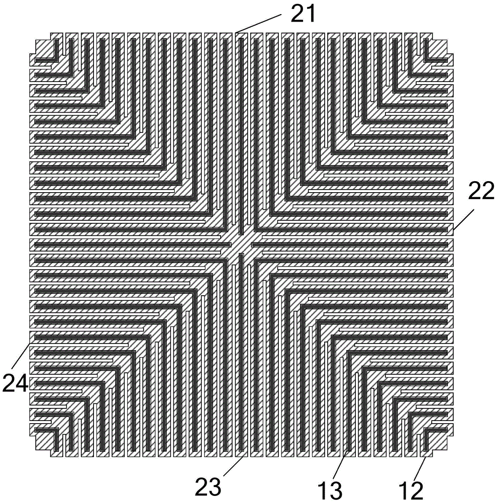
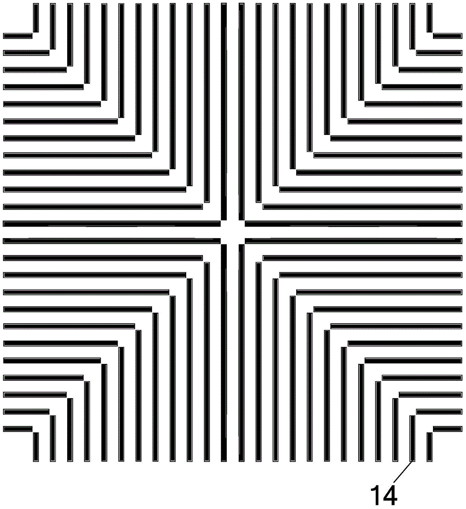
[0024] A plurality of p-type active regions 13 formed by implantation in the plurality of n wells 12; wherein, as figure 2 The above is a schematic structural diagram of a P-type substrate, the n-type well region is rectangular, and the diagonal line of the n-type well region divides the n-type well region into four triangular regions (21-24). The p-type active regions 13 are equidistantly distributed in parallel on each t...


PUM


Abstract

The invention provides an inductor substrate isolation structure of an integrated circuit. The inductor substrate isolation structure comprises a p-type substrate, an n-type well region formed in the p-type substrate and including a plurality of n wells, a plurality of p-type active regions formed in the plurality of n wells through injection, a polycrystalline silicon shielding layer covering the n-type well region and including a plurality of strips of n-type polycrystalline silicon, a metal layer covering the polycrystalline silicon shielding layer, and an inductor covering the metal layer, wherein each strip of n-type polycrystalline silicon covers two adjacent n wells, the plurality of strips of n-type polycrystalline silicon are spaced from each other by the p-type active regions, the metal layer is of an X-shaped metal structure which is arranged in the diagonal position of the n-type well region, and the center point of the inductor coincides with the center point of the X-shaped metal structure. By adopting the inductor substrate isolation structure of the invention, the electromagnetic loss of the inductor to the substrate can be effectively reduced, the coupling capacitance between the inductor, the shielding layer and the substrate can be reduced, and the quality factor and working frequency of the inductor can be improved.

Description

technical field [0001] The invention relates to the technical field of radio frequency integrated circuits, in particular to an inductive substrate isolation structure of an integrated circuit. Background technique [0002] The quality factor of the inductor in the radio frequency integrated circuit is also called the Q value and the operating frequency of the inductor plays a crucial role in the performance of the radio frequency circuit. The isolation of the inductor substrate will seriously affect the quality factor and operating frequency of the inductor. , affecting the performance improvement of some radio frequency circuits. The isolation technology for inductor substrates in modern integrated circuits continues to develop, and various substrate isolation technologies have emerged. The isolation effects are also different. In recent years, isolation technologies have also been greatly improved. [0003] In modern radio frequency integrated circuits, there are two typ...

Claims


Application Information

Patent Timeline
IPC IPC(8): H01L23/522
Inventor 刘志坚
Owner ZHUHAI JIELI TECH
Learn More