Automatic control system used for rolling force of burring roller and control method thereof

An automatic control system and deburring technology, applied in the direction of rolling force/roll gap control, etc., can solve the problems of poor adjustment accuracy, small range and inability to adapt

Inactive Publication Date: 2014-10-01
CHINA NAT HEAVY MACHINERY RES INSTCO
View PDF5 Cites 5 Cited by
  • Summary
  • Abstract
  • Description
  • Claims
  • Application Information

AI Technical Summary

Problems solved by technology

[0003] The purpose of the present invention is to overcome the poor adjustment precision of the roll rolling force and the small range of the existing deburring device, which cannot adapt to the large plastic deformation coefficient and high-efficiency deburring of workpieces processed by different materials

Method used


Image

  • Automatic control system used for rolling force of burring roller and control method thereof
  • Automatic control system used for rolling force of burring roller and control method thereof
  • Automatic control system used for rolling force of burring roller and control method thereof

Examples


Embodiment 1

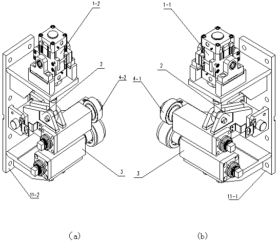
[0032] Embodiment 1, in conjunction with attached Figure 1-3 describe.

[0033] An automatic control system for the rolling force of a deburring roll, including a left deburring device 11-1 and a right deburring device 11-2 arranged in mirror images; (the left deburring device includes a swing frame 2 fixed on a frame The upper part of the swing frame 2 is equipped with a first cylinder 1-1 connected thereto, the lower part of the swing frame 2 is equipped with a movable pressure roller 4-1 fixed thereto, and a fixed support frame 3 at the lower part of the movable pressure roller 4-1 ; The structure of the right deburring device is consistent with that of the left deburring device) The right deburring device 11-2 includes a second cylinder 1-2, and the left deburring device 11-1 includes a first cylinder 1-1, so The automatic control system also includes a pneumatic control unit; the first cylinder 1-1 and the second cylinder 1-2 are connected with the pneumatic control ...

Embodiment 2

[0036] Embodiment 2, in conjunction with attached Figure 1-3 describe.

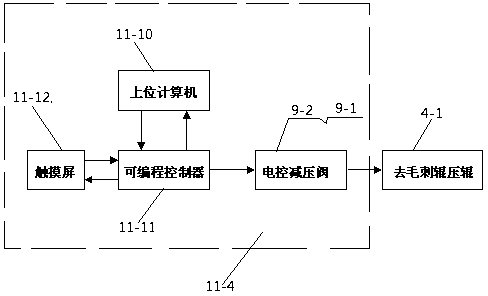
[0037] On the basis of the foregoing embodiments, the control system 11-4 includes a host computer 11-10, a programmable controller 11-11 connected to the host computer 11-10, a touch screen 11 connected to the programmable controller 11-11 -12 and electric control pressure relief valve (electric control pressure relief valve one 9-1, electric control pressure relief valve two 9-2);

[0038] Input the physical parameters and processing instructions of the workpiece to the programmable controller 11-11 through the touch screen 11-12;

[0039] Described programmable controller 11-11 receives touch screen 11-12 to execute command and physical parameter and model it; Control force, and converted to the electrical signal input of the electronically controlled pressure reducing valve (electrically controlled pressure reducing valve 1 9-1, electronically controlled pressure reducing valve 2 9-2), the electr...

Embodiment 3

[0042] Embodiment 3, in conjunction with attached Figure 1-3 describe.

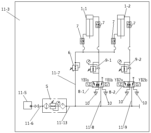
[0043] On the basis of the foregoing embodiments, one-way throttle valves 7 are respectively provided between the pressure reducing valve 6 and the rod chambers of the first cylinder 1-1 and the second cylinder 1-2.

[0044] A one-way throttle valve 7 is arranged between the first cylinder 1-1 and the rodless cavity of the first cylinder 1-1; One-way throttle valve 7 is arranged between the rodless cavity of 2.

[0045] A muffler 10 is respectively installed on the two-position five-way reversing valve two 8-2 and the two-position five-way reversing valve one 8-1.

[0046] In this scheme, one-way throttle valves are arranged on the first air path, the second air path, and the third air path near the gas ports of the first cylinder and the second cylinder to ensure the speed of the adjustment cylinder. The preferred design of the muffler makes the The exhaust sound is reduced to a minimum d...


PUM


Abstract

The invention provides an automatic control system used for a rolling force of a burring roller and a control method thereof. The automatic control system comprises a left burring device and a right burring device, wherein the right burring device comprise a second cylinder; the left burring device comprises a first cylinder; a pneumatic control unit is connected with the first cylinder and the second cylinder in a controlling manner; an electric control unit is connected with the pneumatic control unit in the controlling manner. The automatic control method comprises the following steps of: A, obtaining and recording thickness, yield strength, size, plastic deformation coefficient and hardness of a processed work-piece; B, inputting results obtained in the step A into the electric control unit; C, starting up the automatic control system, and starting controlling the automatic control unit after an electrical control reducing valve receives an electric control signal; D, adjusting the size of the rolling force between a movable pressing roller of the debugging device and a processing belt material based on the control result obtained in the step B, and displaying in a display screen. According to the scheme, the adjusted rolling force of the burring device is high in precision, the processing materials to be used are wide in range, and the rate of finished products in the processing process is extremely high; the automatic control system used for the rolling force of the burring roller and the control method thereof can be widely applied to the belt material processing field.

Description

technical field [0001] The invention relates to the technical field of metal strip processing equipment, in particular to an automatic control system and a control method for the rolling force of a deburring roll. Background technique [0002] Strip trimming disc shears are generally set on the finishing line. Because the blade is a rotating disc, it can continuously cut the moving strip. The strips that need to be trimmed include mild steel, high-strength steel, and stainless steel. For steel types such as silicon steel and tin plate, under reasonable shear conditions, the burr height is generally 5% of the plate thickness, and the burr requirement is less than 0.01 mm under the condition of using deburring rollers. When the strip is relatively thin, And when the yield limit of the strip is very low, the minimum limit of the rolling force required for deburring can be zero at this time, and once the pressure is too high, it will leave indentations on the finished strip, but...

Claims


Application Information

Patent Timeline
Patent Type & Authority Applications(China)
IPC IPC(8): B21B37/58
Inventor 冯沙冀俊杰许展望任玉成张康武高聪敏
Owner CHINA NAT HEAVY MACHINERY RES INSTCO
Why Eureka
Try Eureka