Tapping device for punching chassis

A technology of tapping device and casing, applied in positioning device, clamping device, drilling/drilling equipment, etc., can solve the problems of low processing efficiency, many processing procedures, long processing time, etc., and achieve high processing efficiency, The effect of fewer processing steps and shorter processing time

Inactive Publication Date: 2014-10-01
NINGBO LIONBALL VENTILATOR
View PDF9 Cites 17 Cited by
  • Summary
  • Abstract
  • Description
  • Claims
  • Application Information

AI Technical Summary

Problems solved by technology

[0003] At present, when processing the above-mentioned threaded holes, it is necessary to punch holes on the left side, right side and bottom surface of the casing respectively, and then tap the holes on the left side, right side

Method used


Image

  • Tapping device for punching chassis
  • Tapping device for punching chassis
  • Tapping device for punching chassis

Examples


Embodiment Construction

[0029] The present invention will be described in further detail below in conjunction with the accompanying drawings and specific embodiments.

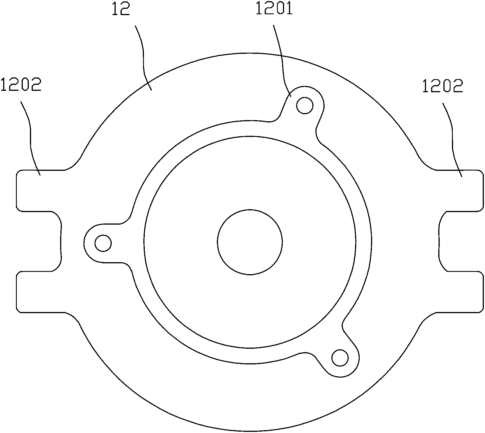
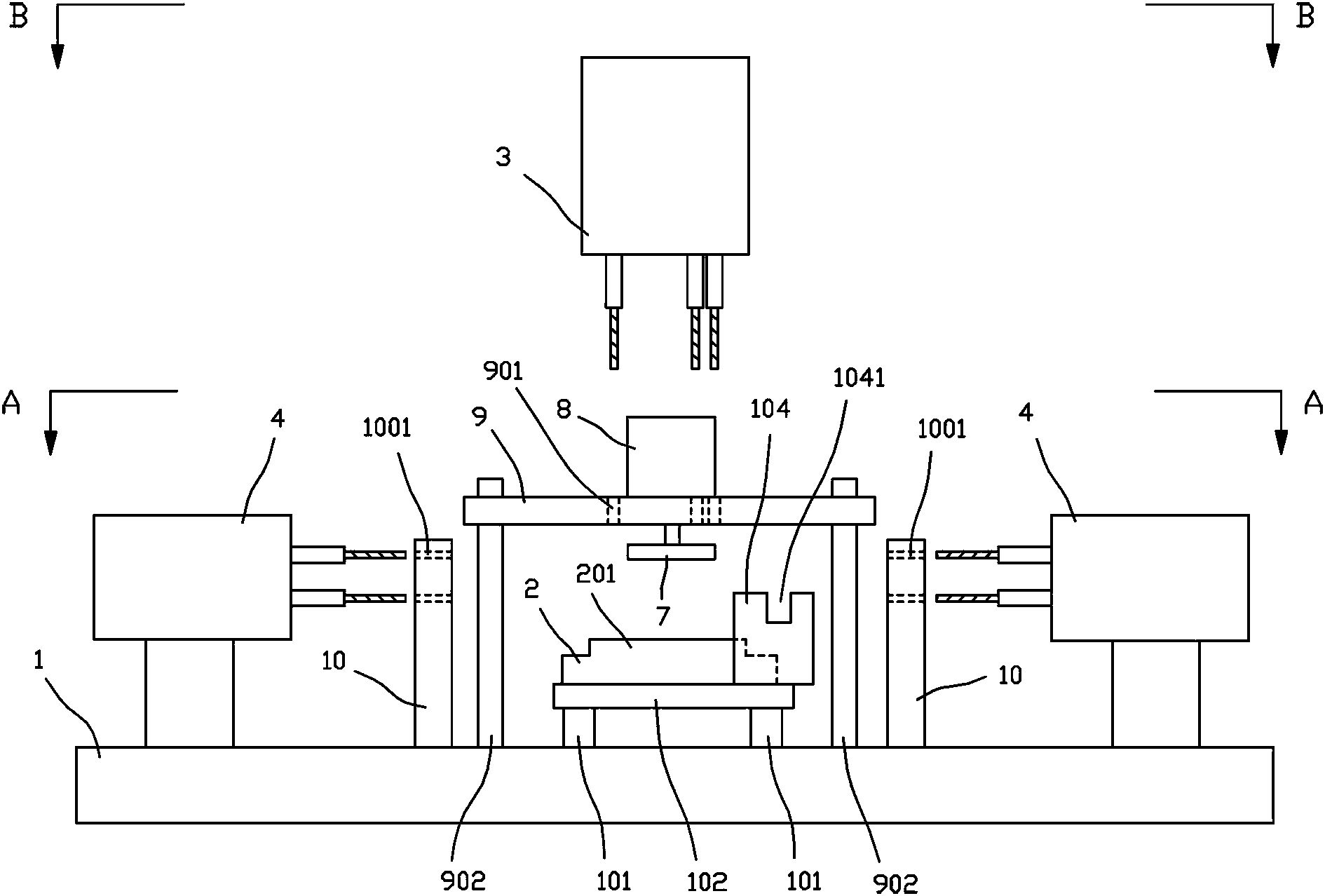
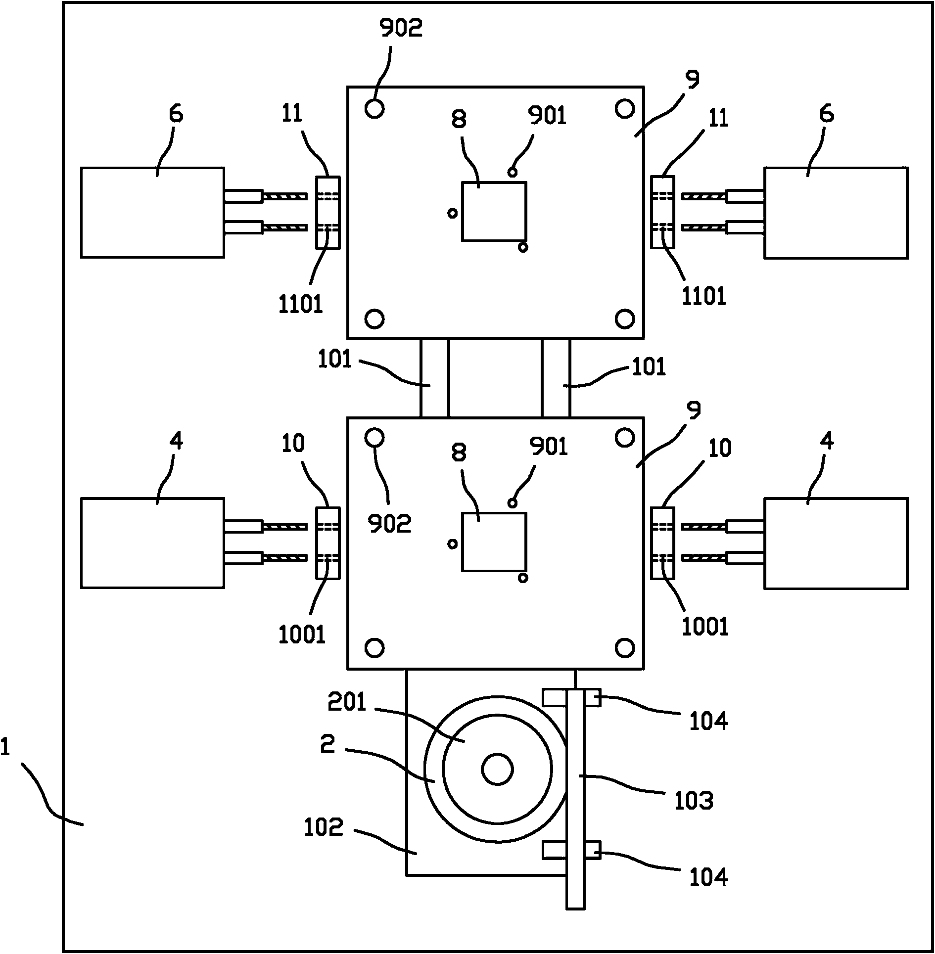
[0030] Depend on Figure 2 to Figure 5 As shown, the casing punching and tapping device of the present invention includes a workbench 1, which is arranged horizontally. , the base 2 is fixed on the sliding seat 102, and the sliding seat 102 is driven by a cylinder. When the casing is installed, the bottom of the casing is turned upwards, and the mouth of the casing is placed downwardly on the circular boss 201 on the base 2, so that the casing is fixed.

[0031] The workbench 1 is provided with a punching assembly and a tapping assembly, and the punching assembly and the tapping assembly are arranged sequentially along the moving direction of the base 2, that is to say, the punching assembly is arranged at the front end of the workbench 1, and the tapping assembly is arranged at the working The back end of Desk 1.

[0032] The punc...


PUM


Abstract

The invention discloses a tapping device for punching a chassis. The tapping device comprises a horizontally arranged workbench, a pedestal which can linearly move to and fro and is arranged on the workbench for holding the chassis, and a punching assembly and a tapping assembly sequentially arranged along the moving direction of the pedestal, wherein the punching assembly can be used for simultaneously punching in the left side, right side and bottom surface of the chassis; the tapping assembly can be used for simultaneously tapping on the left side, right side and bottom surface of the chassis. According to the tapping device for punching the chassis, the machining efficiency of thread holes in the chassis is high.

Description

technical field [0001] The invention relates to a device for drilling and tapping a motor casing. Background technique [0002] like figure 1 As shown, when producing the casing 12 of the motor, after the casing 12 is die-casted, the bottom surface of the casing 12 is provided with three first mounts 1201 evenly distributed in the circumferential direction, and the two sides of the casing 12 (the left side , right side) are provided with two second mounts 1202, one threaded hole needs to be processed on each first mount 1201, and two threaded holes need to be processed on each second mount 1202, so that the machine Shell 12 just can be installed and fixed through above-mentioned threaded hole. [0003] At present, when processing the above-mentioned threaded holes, it is necessary to punch holes on the left side, right side and bottom surface of the casing respectively, and then tap the holes on the left side, right side and bottom surface of the casing respectively. Wire...

Claims


Application Information

Patent Timeline
IPC IPC(8): B23P23/02B23Q3/08B23Q1/25B23B49/02
CPCB23B49/023B23P23/02B23Q1/25B23Q3/08B23Q2703/04
Inventor 纪重斌陈国龙郑忠华王海艇张建洪
Owner NINGBO LIONBALL VENTILATOR
Why Eureka
Try Eureka