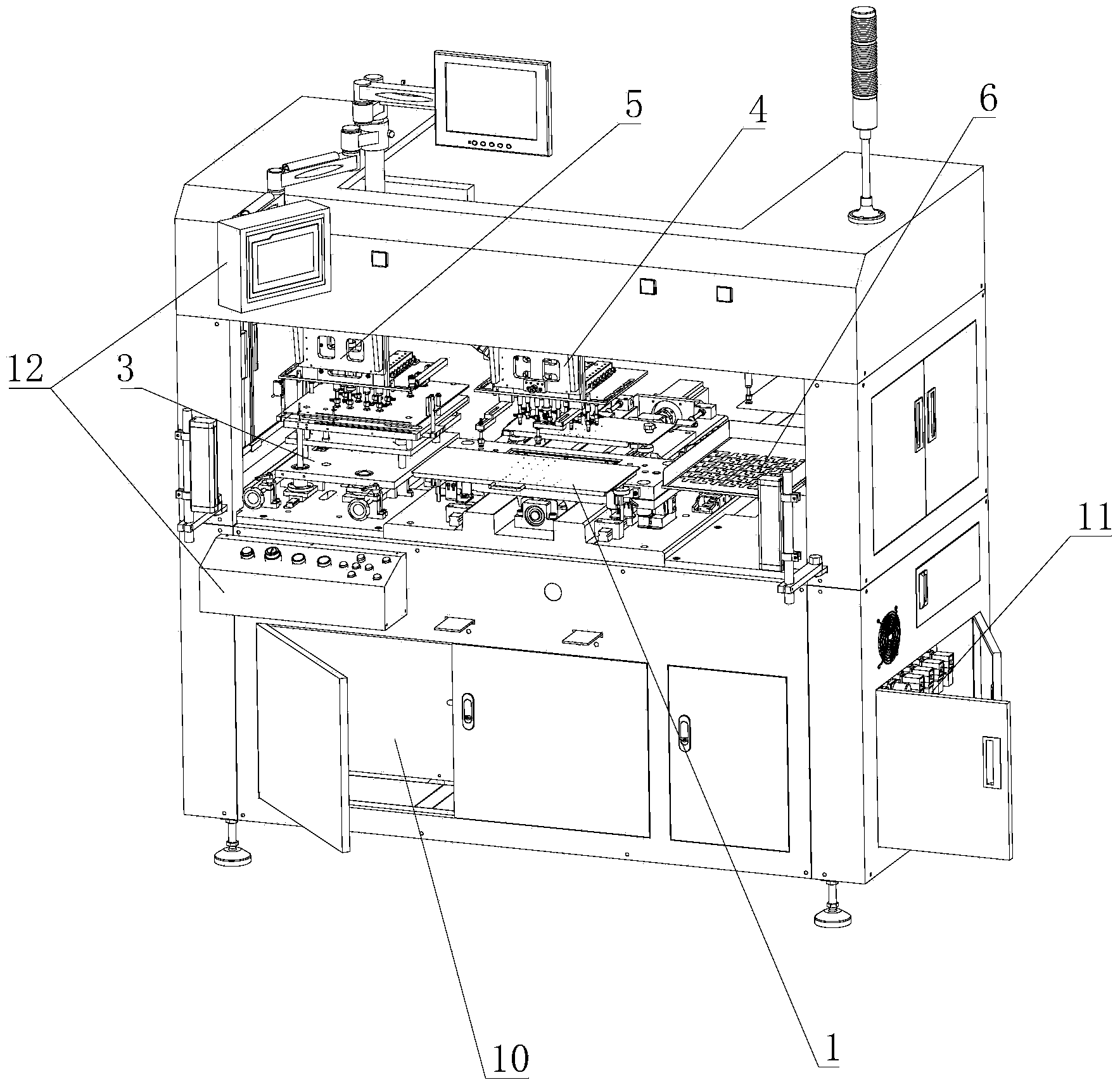
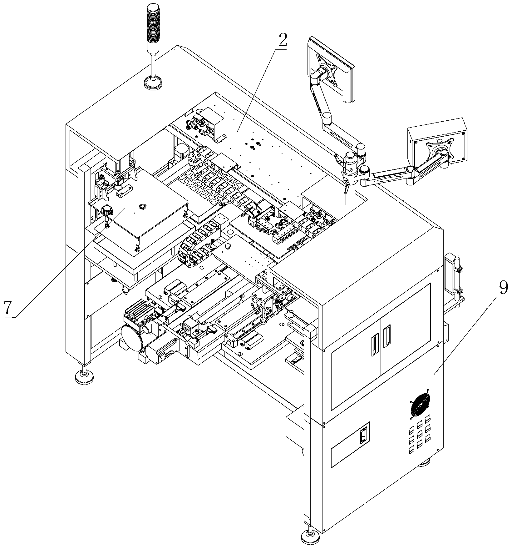
Fully-automatic single blanking mechanical arm
A manipulator, fully automatic technology, applied in metal processing and other directions, can solve the problems of high labor intensity, high labor intensity, unstable personnel, etc., and achieve the effect of reducing labor intensity, saving labor, and improving production rate.
- Summary
- Abstract
- Description
- Claims
- Application Information
AI Technical Summary
Problems solved by technology
Method used
Image
Examples
Embodiment 1
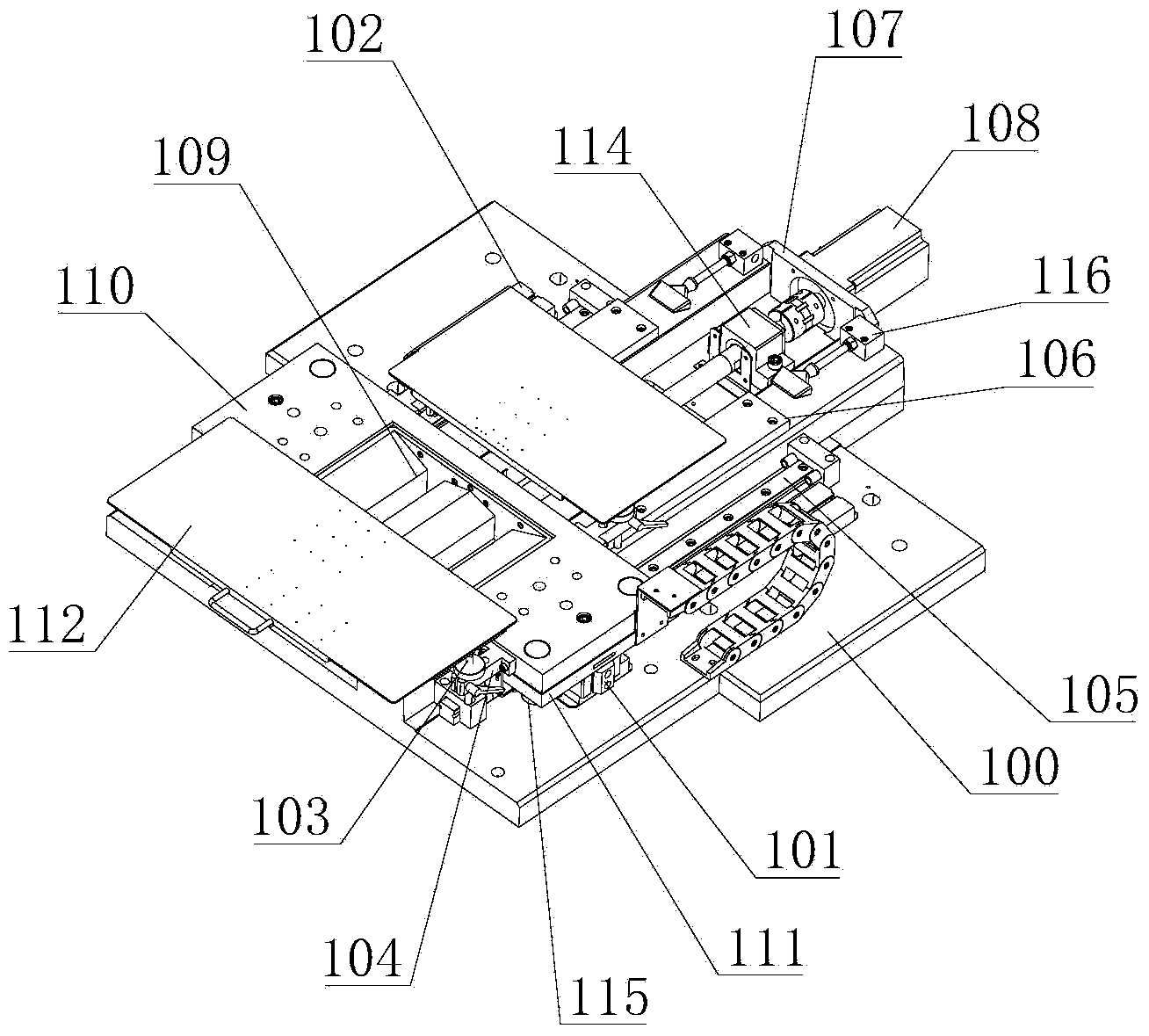
[0065] Further, such as image 3 In the punching device shown above:
[0066] The second substrate mechanism includes a second bottom plate 100, a sensor shield 102, a tray lifting rod 103, a tray seat 104, a funnel 109 and a cleaning air blowing seat 116;
[0067] The Y-axis translation mechanism includes a cylinder 101, a linear slide rail 105, a mold support block 106, a servo motor mounting plate 107, a servo motor 108, a ball screw 113, and a ball screw mounting seat 114;
[0068] The mold installation mechanism includes a mold installation plate 110 , a moving plate 111 and a guide post / guide sleeve 115 .
[0069] A linear slide rail 105 is installed on the second bottom plate 100, and a moving plate 111 is slidably connected to the linear slide rail 105. A mold mounting plate 110 is arranged on the moving plate 111, a funnel 109 is installed on the mold mounting plate 110, and a tray panel 112 is arranged above the funnel 109. .
Embodiment 2
[0071] Further, such as Figure 4 , 5 As shown, the above-mentioned horizontal transport device includes a transporter plate 201, a stepper motor 202, a synchronous wheel 203, a synchronous belt 204, a stepper motor mounting plate 205, a synchronous wheel seat 206, a synchronous wheel 207, a synchronous belt 208, and a linear slide rail 209 , Slide rail pad 210, idler seat 211, timing belt tensioning mechanism 212, limit block 213, timing belt fixing block 214, tank chain 215.
[0072]The two ends of one side surface of the conveyor plate 201 are respectively provided with a stepper motor 202 through a stepper motor mounting plate 205, the output shaft of the stepper motor 202 is connected with a synchronous wheel 203, and the synchronous wheel 203 is sleeved on the synchronous belt 204, and the synchronous belt 204 is connected to the two stepping motors 202 through the synchronous wheel 207 arranged on the synchronous wheel base 206 on the other side of the conveyor plate 2...
Embodiment 3
[0074] Further, such as Figure 6 , 7 In the above-mentioned feeding tray device as shown:
[0075] The X-axis translation mechanism includes the workpiece position adjustment knob 302 , the workpiece position fixing block 303 , the position fixing handle 304 , the position adjustment wire motherboard 305 , the position adjustment bearing seat 306 and the product position sensor 307 .
[0076] The lifting plate mechanism includes a third base plate 301, a lifting base plate 308 of workpieces to be processed, a lifting plate 309, a lifting frame panel 310, a tray base plate 311, a tray panel 312, a lift guide shaft 317, a lift guide bearing 318, and a tray panel support column 319 , positioning the central axis of rotation 320 of the needle.
[0077] The workpiece adjustment mechanism includes a product position sensor 307 , a positioning pin 313 of the workpiece to be processed, a positioning pin mounting bar 314 , a linear slide rail 315 and a position adjustment rotating m...
PUM
 Abstract
Description
Claims
Application Information
 - R&D
- Intellectual Property
- Life Sciences
- Materials
- Tech Scout
- Unparalleled Data Quality
- Higher Quality Content
- 60% Fewer Hallucinations
Browse by: Latest US Patents, China's latest patents, Technical Efficacy Thesaurus, Application Domain, Technology Topic, Popular Technical Reports.
© 2025 PatSnap. All rights reserved.Legal|Privacy policy|Modern Slavery Act Transparency Statement|Sitemap|About US| Contact US: help@patsnap.com


