Backlight module based on quantum dot light guide plate

A technology of backlight module and light guide plate, which is applied to optical elements, point light sources, optics and other directions for changing the spectral characteristics of emitted light, can solve the problems of low temperature, low light transmittance and large amount of quantum dots, etc. Achieve the effect of good heat dissipation, wide color gamut and high light efficiency

Active Publication Date: 2014-10-01
NANJING BREADY ELECTRONICS CO LTD
View PDF5 Cites 46 Cited by
  • Summary
  • Abstract
  • Description
  • Claims
  • Application Information

AI Technical Summary

Problems solved by technology

The quantum dot film is far away from the LED and the temperature is low. However, this method uses a large amount of quantum dots

Method used


Image

  • Backlight module based on quantum dot light guide plate
  • Backlight module based on quantum dot light guide plate
  • Backlight module based on quantum dot light guide plate

Examples


Embodiment 1

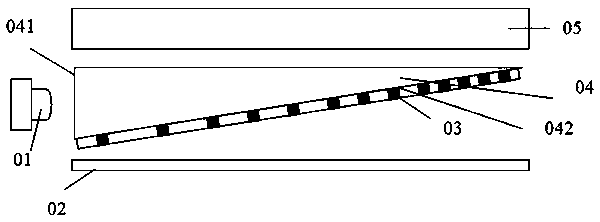
[0026] refer to figure 1 , is a schematic diagram of the first embodiment of the backlight module provided by the present invention. The backlight module includes a blue light source 01 , a light guide plate 04 , a reflection sheet 02 disposed below the light guide plate 04 , and an optical module 05 disposed above the light guide plate 04 . The blue light source 01 is located at the side of the light guide plate 04 .

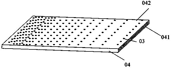
[0027] The light guide plate 04 has an upper surface 041 and a lower surface 042, and the lower surface 042 has light guide dots 03 distributed thereon. The light guide dots 03 are uniformly circular, with a diameter between 0.02 mm and 1 mm. The light guide dots 03 are distributed from dense to sparse on the lower surface 042 of the light guide plate, and the distribution density is between 2.5% and 76%. Use light simulation software to regulate the distribution of light guide points. According to the relative positional relationship between the light guide ...

Embodiment example 2

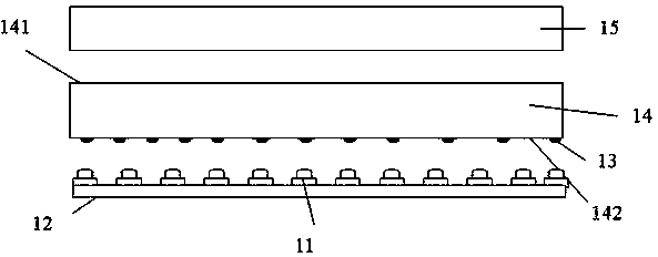
[0033] refer to image 3 , is a schematic diagram of the second embodiment of the backlight module provided by the present invention. The backlight module includes a blue light source array 11 , a light guide plate 14 , a reflection sheet 12 disposed below the light guide plate 14 , and an optical module 15 disposed above the light guide plate 14 . The blue light source array 11 is located under the light guide plate 14 .

[0034] The light guide plate 14 has an upper surface 141 and a lower surface 142 , and light guide dots 13 are distributed on the lower surface 142 . The light guide dots 13 are uniformly circular, with a diameter between 0.02 mm and 1 mm. The light guide dots 13 are distributed from dense to sparse arrays on the lower surface 142 of the light guide plate, and the distribution density is between 2.5% and 76%. between. Use light simulation software to regulate the distribution of light guide points. According to the relative positional relationship betwee...


PUM

PropertyMeasurementUnit
Thicknessaaaaaaaaaa
Diameteraaaaaaaaaa
Heightaaaaaaaaaa

Abstract

The invention discloses a backlight module based on a quantum dot light guide plate, and the backlight module comprises a light source, a light guide plate, an optical module arranged above the light guide plate, and a reflective sheet arranged below the light guide plate, wherein the thickness of the light guide plate is in the range from 0.1 to 6mm, the lower surface of the light guide plate is provided with light guide mesh points which are made from a composite material including quantum dots and diffusion particles, and quantum dot lights stimulated by the light source and light source lights are compounded into white lights. In the backlight module, the quantum dots are added into the light guide mesh points so that monochromatic lights can be converted into the white lights, the backlight module has the following advantages of excellent heat dissipation, wide tonal range and high luminous efficiency. In preparation, only a silk screen printing slurry is changed instead of changing traditional processes for manufacturing the backlight module.

Description

technical field [0001] The invention belongs to the field of backlight module preparation, and in particular relates to a backlight module based on a quantum dot light guide plate. Background technique [0002] Liquid crystal displays have become mainstream products in the display field today. Since the liquid crystal panel itself does not emit light, a backlight module is required to provide a light source. At present, there are three main types of white LEDs used in backlight modules. One is that the LED unit forms white light by mixing LED light sources of three primary colors, which is costly and difficult to control; Encapsulating the chip and the phosphor layer together has problems such as heat dissipation and low light efficiency; the third is to excite quantum dots that emit red and green light through blue LEDs, and the three colors of light are mixed into white light. [0003] A quantum dot is a nanocrystal having a diameter of several to tens of nanometers, is ...

Claims


Application Information

Patent Timeline
IPC IPC(8): F21S8/00F21V9/10G02B6/00F21Y101/02F21V9/40F21Y115/10
Inventor 郭太良陈恩果叶芸徐胜胡海龙张典
Owner NANJING BREADY ELECTRONICS CO LTD
Why Eureka
Try Eureka