Moderate temperature straight all-glass vacuum heat collecting tube

A vacuum heat collecting tube and straight-through technology, which is applied in the field of solar heat utilization, can solve the problems of not being able to effectively compensate for large differences in expansion, low working temperature, and inconvenient connection in series, so as to reduce the difficulty of sealing and the failure rate. The effect of reducing the connection difficulty and improving the reliability

Active Publication Date: 2014-10-01
NANJING UNIV OF TECH
View PDF5 Cites 5 Cited by
  • Summary
  • Abstract
  • Description
  • Claims
  • Application Information

AI Technical Summary

Problems solved by technology

Due to the poor toughness of the glass, the corrugated glass structure cannot effectively compensate for the large difference in expansion, and the working temperature is lower than 100°C
In addition, the nozzles at both ends of the heat collecting tube are also of glass sealing structure, which is not convenient for series connection

Method used


Image

  • Moderate temperature straight all-glass vacuum heat collecting tube
  • Moderate temperature straight all-glass vacuum heat collecting tube
  • Moderate temperature straight all-glass vacuum heat collecting tube

Examples


Embodiment 1

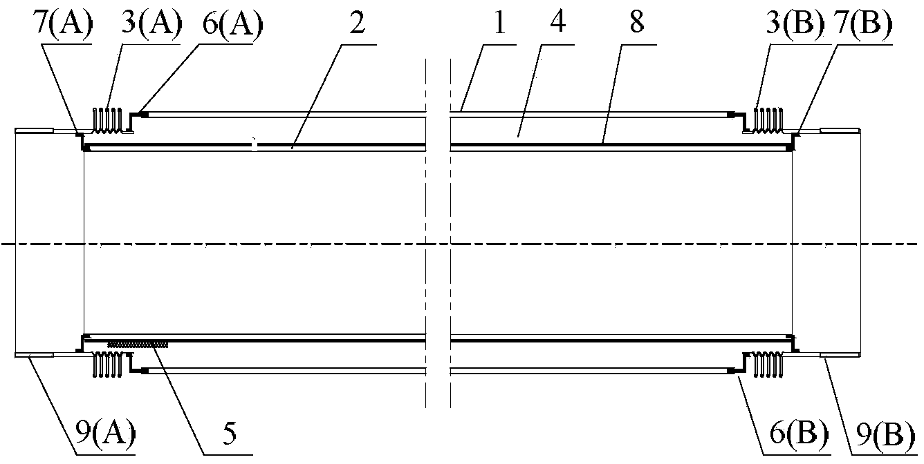
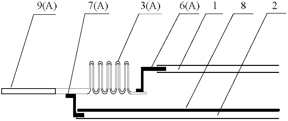
[0028] Such as figure 1 As shown, the present invention discloses a medium-temperature straight-through all-glass vacuum heat collecting tube, which is composed of a glass outer tube 1, a glass inner tube 2, a corrugated expansion joint 3 and a metal connecting tube 9; the glass outer tube 1 and the glass inner tube 2 The space is a vacuum space 4, the outer surface of the glass inner tube 2 is coated with a selective absorption coating 8 with high absorption rate and low emissivity; 1 One end is sealed to one end of the first wave expansion joint 3 (A) through the first transition coupling ring 6 (A), and the other end is sealed to the second wave expansion joint 3 (B) through the second transition coupling ring 6 (B) One end is sealed; the other ends of the first wave expansion joint 3 (A) and the second wave expansion joint 3 (B) respectively pass through the third transition coupling ring 7 (A) and the fourth transition coupling ring 7 (B) and the inner glass Both ends of...

Embodiment 2

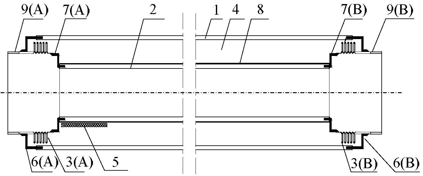
[0031] Such as image 3 Shown is another embodiment of the present invention, the corrugated expansion joint 3 is a built-in type, that is, it is placed inside the glass outer tube 1; the diameter of the glass inner tube 2 is 30mm, and the length is 2m; the diameter of the glass outer tube 1 is The glass inner tube 2 is 10mm larger; the glass outer tube 1 and the glass inner tube 2 are made of borosilicate glass 5.0; the corrugated expansion joint 3 is made of stainless steel, the waveform is U-shaped, and the wave number is 1; the transition connection ring I6 and the transition connection ring II7 The material has an expansion coefficient of 4×10 -6m / (m·℃) Fe-Ni-Co Kovar alloy, sealed with glass outer tube 1, glass inner tube 2 and corrugated expansion joint 3 respectively by fusion sealing connection and solder welding process; the vacuum of vacuum space 4 The degree is 0.01Pa; the absorptivity of the selective absorbing coating is 96%, and the emissivity is 14%. All the ...

Embodiment 3

[0034] In yet another embodiment of the present invention, the corrugated expansion joint 3 is Ω-shaped, and the length of the glass outer tube is 4m; the material of the transition coupling ring I6 and the transition coupling ring II7 is an expansion coefficient of 12×10 -6 m / (m·℃) of stainless steel; sealing with glass outer tube 1, glass inner tube 2 and corrugated expansion joint 3 by fusion sealing connection and solder welding process respectively; the vacuum degree of the vacuum space is 5×10 -5 Pa. All the other structural forms and parameters are the same as in Example 1.

[0035] The heat collecting tube in this embodiment is used in the compound parabolic concentrating system, the heat collecting efficiency of the heat collecting tube reaches 65% to 75%, and the heat collecting temperature range is 0 to 150°C; when the working temperature is 150°C, the thermal stress of the heat collecting tube is higher than that of the straight-through metal- The glass vacuum hea...


PUM


Abstract

The invention relates to a moderate temperature straight all-glass vacuum heat collecting tube which comprises a glass outer tube (1), a glass inner tube (2), a first bellows expansion joint (3(A)), a second bellows expansion joint (3(B)), a first metal connecting tube (9(A)) and a second metal connecting tube (9(B)), wherein one end of the glass outer tube (1) is in sealing connection with one end of the first bellows expansion joint (3(A)) via a first transition connecting ring (6(A)); the other end of the glass outer tube (1) is in sealing connection with one end of the second bellows expansion joint (3(B)) via a second transition connecting ring (6(B)); the other ends of the bellows expansion joints are in sealing connection with the two ends of the glass inner tube (2) via transition connecting rings; and the first metal connecting tube (9(A)) and the second metal connecting tube (9(B)) are welded at outer side orifices of the first bellows expansion joint (3(A)) and the second bellows expansion joint (3(B)) respectively. The tube is lower in cost and sealing connection difficulty, and is applicable to solar moderate temperature heat utilization systems of industrial heating, heat energy refrigeration and the like.

Description

technical field [0001] The invention relates to a medium-temperature through-type all-glass vacuum heat collection tube, which is used in a solar energy medium-temperature heat collection system and belongs to the technical field of solar heat utilization. Background technique [0002] Solar energy medium and high temperature heat utilization technology, including industrial heat, air conditioning and refrigeration, and solar thermal power generation, is a research hotspot. The trough collector is currently the most commercialized solar medium temperature collector. Straight-through metal-glass vacuum collector tubes are the core components of current trough collectors as components to realize light-to-heat conversion. Commercial straight-through metal-glass vacuum heat collectors include UVAC heat collectors produced by Siemens and PTR heat collectors produced by Schott. The metal-glass sealing is relatively difficult, and the key technology of sealing is monopolized by fo...

Claims


Application Information

Patent Timeline
Patent Type & Authority Applications(China)
IPC IPC(8): F24J2/46
CPCY02E10/40Y02P80/20
Inventor 朱跃钊王银峰许佳慧陈海军钱裕杨丽
Owner NANJING UNIV OF TECH
Why Eureka
Try Eureka