
Milling process parameter optimization method

A technology of process parameter optimization and process parameters, which is applied in the field of cutting processing technology, can solve problems such as not being able to meet high-speed cutting processing, affecting the machining accuracy of parts, the service life of machine tool spindles and tools, and restricting cutting processing efficiency.

Active Publication Date: 2014-10-01
TONGJI UNIV
View PDF5 Cites 29 Cited by
  • Summary
  • Abstract
  • Description
  • Claims
  • Application Information

AI Technical Summary

Problems solved by technology

Chattering will cause ripples on the machined surface, causing drastic changes in cutting force. Chattering will seriously restrict the efficiency of cutting processing, affect the machining accuracy of parts, and the service life of machine tool spindles and tools.
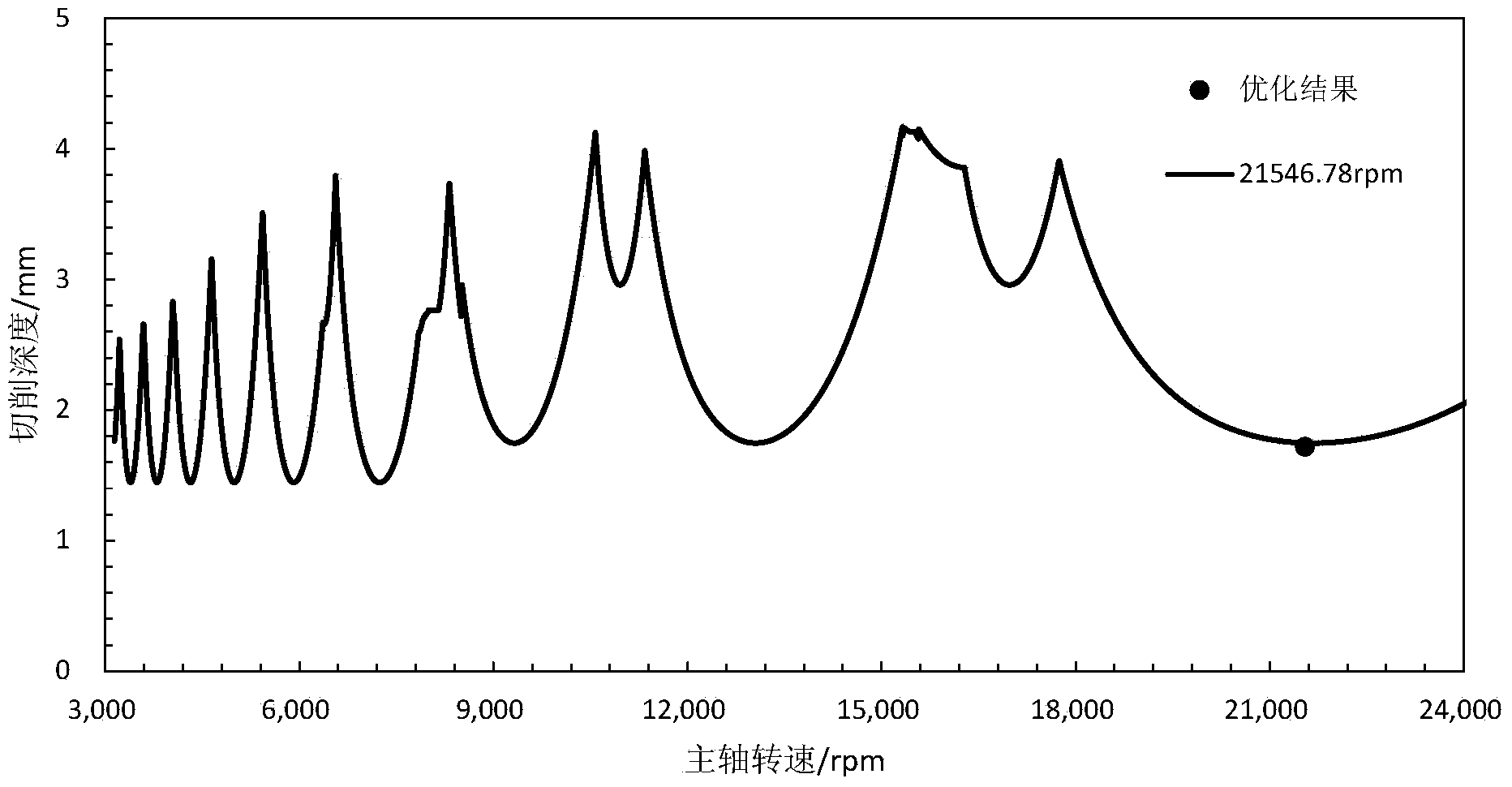
[0003] The cutting stability diagram provides the cutting speed and the corresponding limit cutting depth without chatter. In the current research on the optimization of milling process parameters, the main problems are: 1) the factors affecting cutting stability are not considered, 2) the cutting The stability diagram is introduced into the optimization model as a constraint that does not change during cutting
It is difficult to obtain the optimal milling process parameters by simplifying the cutting stability diagram to a fixed value constraint or optimizing the milling process parameters without considering the cutting stability
[0004] With the development of high-speed electric spindles and new material cutting tools, high-speed cutting has been widely used in various industries, especially aerospace, automobile industry and mold processing. Traditional cutting parameter optimization methods can no longer meet the needs of high-speed cutting. needs

Method used


Image

  • Milling process parameter optimization method
  • Milling process parameter optimization method
  • Milling process parameter optimization method

Examples


Embodiment Construction

[0044] The present invention will be further described below in conjunction with the embodiments shown in the accompanying drawings.

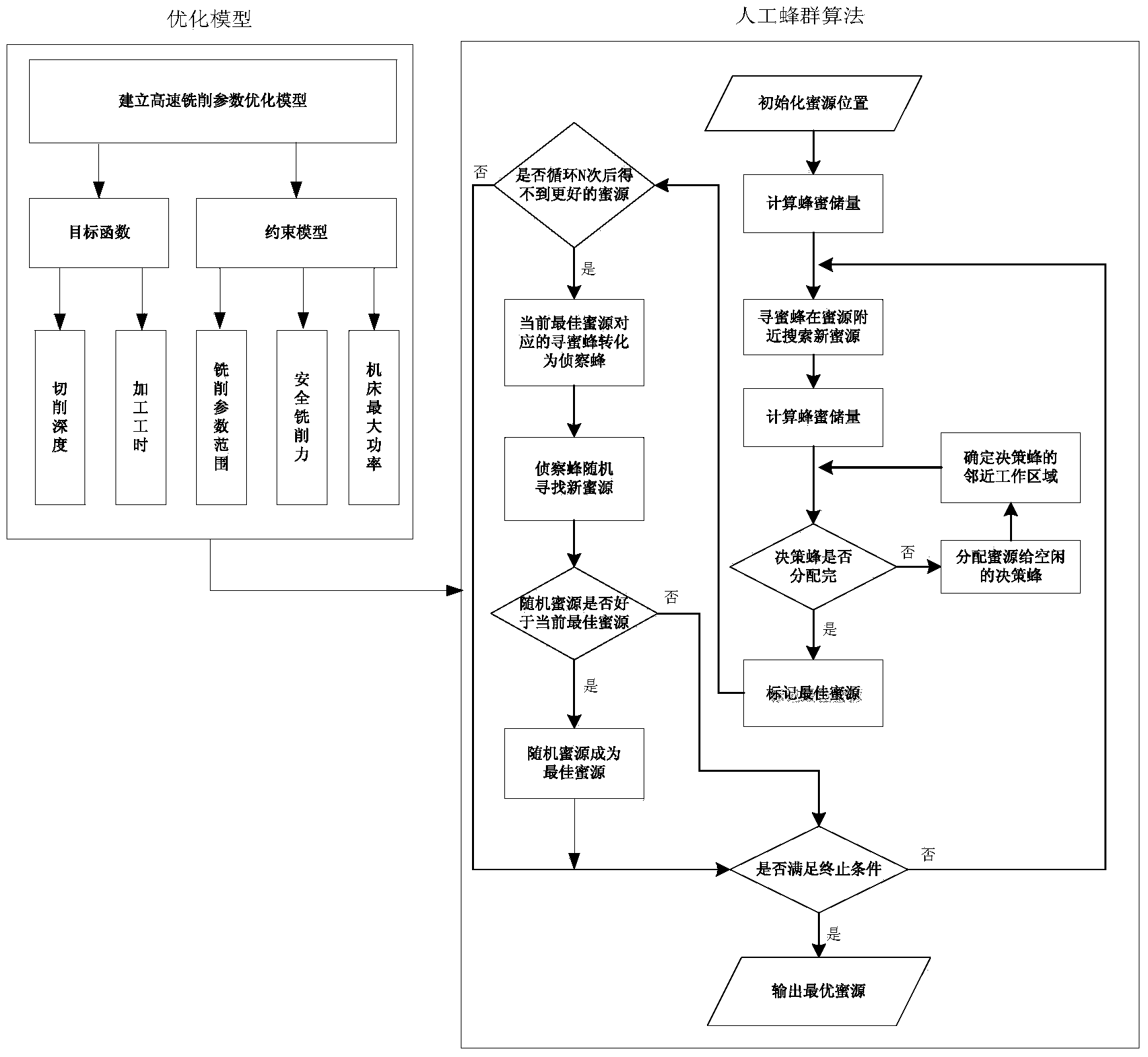
[0045] Aiming at the deficiencies of the prior art, the present invention proposes a milling process parameter optimization method based on cutting stability and applicable to the high-speed milling process for the fields of aerospace, automobiles and moulds. The method first establishes a high-speed milling process parameter optimization model , and then according to the artificial bee colony algorithm, the established optimization model is calculated to obtain the optimal combination of milling process parameters that can obtain the maximum productivity in the non-chatter state (that is, the cutting stable state).

[0046] In order to achieve the purpose of the invention, the high-speed milling process parameter optimization model in the present invention considers cutting stability and productivity, and the model satisfies the following relat...


PUM


Abstract

The invention provides a milling process parameter optimization method and belongs to the field of cutting machining processes. The coupling effect of a machining device dynamic behavior and the high-speed milling process is considered in the method, the maximum milling extreme cutting depth changing with the rotating speed of a machine tool spindle and shortest machining time of single part are regarded as optimization targets, a milling process parameter optimization model based on cutting stability and productivity is established, and optimal milling process parameters of a milling process parameter combining scheme under the condition that a cutting state is stable when the productivity is maximum are calculated. The milling process parameter optimization method can improve the cutting depth to the most extent during milling, decrease feed times, obtains maximum productivity, meanwhile ensures the cutting stability and avoids flutter. In addition, the milling process parameter optimization method can be applied to the high-speed milling process, the defect that the interactive effect of the machining device dynamic behavior and the milling process parameters is not considered in the high-speed milling process at present is overcome, and optimal high-speed milling process parameters can be obtained.

Description

technical field [0001] The invention belongs to the field of cutting processing technology, and relates to a process parameter optimization method. Background technique [0002] During metal cutting, when the depth of cut exceeds a certain value, processing equipment will chatter. Chatter will cause ripples on the machined surface, causing drastic changes in cutting force. Chatter will seriously restrict the efficiency of cutting, affect the machining accuracy of parts, and the service life of machine tool spindles and tools. [0003] The cutting stability diagram provides the cutting speed and the corresponding limit cutting depth without chatter. In the current research on the optimization of milling process parameters, the main problems are: 1) the factors affecting cutting stability are not considered, 2) the cutting The stability diagram is introduced into the optimization model as a constraint that does not change during cutting. In the high-speed cutting process, du...

Claims


Application Information

Patent Timeline
IPC IPC(8): G05B19/18
Inventor 刘雪梅张正旺李爱平徐立云谭顺利鲍进
Owner TONGJI UNIV
Learn More