Circuit protector

A circuit protector and protector technology, applied in the direction of electric thermal protection switch, heating/cooling contact switch, etc., can solve the problems of uneven shunt of parallel circuits, irregular rising trend, difficult parallel circuits, etc., to reduce material selection requirements, The effect of wide selection of materials and low production level

Active Publication Date: 2014-10-01
BYD CO LTD
View PDF5 Cites 0 Cited by
  • Summary
  • Abstract
  • Description
  • Claims
  • Application Information

AI Technical Summary

Problems solved by technology

Although PTC can achieve multiple protections, the resistance distribution among products is wide and the distribution is uncontrollable. Even for a single product, the resistance will gradually increase during storage and use, and the upward trend is irregular and unrepeatable , showing that the resistance is unstable and uncontrollable. Even for PTCs with the same room temperature resistance, there will be no situation where the rising trend of resistance is exactly the same during storage and use. Therefore, generally PTCs are only used in a single circuit, but It is difficult to be used in parallel circuits, otherwise it will cause problems such as uneven shunting in parallel circuits
The reason for this instability and uncontrollability is that the distribution of materials inside PTC is random and uncontrollable. The process and formula can only try to control this distribution within a certain mean value and range. During the production process, batches There is no repeatability in the distribution between batches and batches, and there is no repeatability in the resistance temperature change of a single product.

Method used


Image

  • Circuit protector
  • Circuit protector

Examples


Embodiment 1

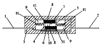
[0031] Product A1 structure: shell, first lead-out end, second lead-out end, switch assembly, heating element and two sets of protective bodies; the protective body is high-expansion filler. The switch assembly includes a first conductive part, a first connecting body, a second conductive part and a second connecting body that are electrically connected in sequence, and one end of the first conductive part electrically connected to the first connecting body is also provided with a first insulating part; A second insulating part is provided at one end of the conductive part electrically connected to the second connecting body, and cavities are provided between the first conductive part and the casing, and between the second conductive part and the casing. The cavity is filled with elastomer.

[0032] The material of each part: shell: alumina ceramics, size 12mm×8mm×6mm; heating element: CPTC, size 6mm×4mm×0.3mm, room temperature resistance 5Ω, working voltage 2-30V; first lead-...

Embodiment 2

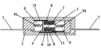
[0034] Product A2 is prepared according to the structure and materials of Example 1, the difference is that: the cavity is a low-expansion filler; the low-expansion filler is insulating ceramics; the shell is zirconia ceramics; the high-expansion filler: chlorinated polyethylene; The first insulating part and the second insulating part: zirconia ceramics; the first conductive part and the second conductive part: tin bronze; the first connecting body and the second connecting body: tin bronze.

Embodiment 3

[0036] Product A3 was prepared according to the structure and materials of Example 1, the difference is that there is no filler in the cavity; the shell is made of zirconia ceramics; the high-expansion filler: polyethylene glycol; the first insulating part and the second insulating part: zirconia Ceramic; the first conductive part and the second conductive part: nickel; the first connecting body and the second connecting body: nickel.


PUM


Abstract

The invention provides a circuit protector, which comprises a case, a first lead-out end, a second lead-out end, a switch assembly, a protection body and a heating body, wherein the first lead-out end and the second lead-out end are respectively led out from the case; the switch assembly, the protection body and the heating body are positioned in the case; the switch assembly and the heating body are connected in parallel with the first lead-out end and the second lead-out end; the protection body controls the on-off state of the switch assembly; and the protection body is a high-expansion filling object. The circuit protector provided by the invention can be used for protection for many times, and in addition, the resistance in the protector is stable.

Description

technical field [0001] The invention belongs to the field of circuit protection, in particular to a circuit protector. Background technique [0002] In circuit protection, metal sheet, FUSE (fuse) or PTC (thermistor) are commonly used as protectors. [0003] When the metal sheet is used as a protector, a bimetal sheet is often used. When the temperature of the metal sheet protector is too high or the current is too large, the metal sheet will be deformed by heat, thereby disconnecting the circuit. When the circuit has an abnormally high current, the metal sheet will heat up rapidly and deform, thus cutting off the circuit. But after the circuit is disconnected, the current of the entire circuit is zero, so that the metal sheet cannot heat itself and maintain deformation, and its temperature will gradually decrease until it returns to the initial state, and the circuit will be turned on again at this time. so repeatedly. [0004] As a protector, FUSE (fuse) realizes over-t...

Claims


Application Information

Patent Timeline
Patent Type & Authority Applications(China)
IPC IPC(8): H01H37/74H01H81/02
Inventor 陈炎李亚飞刘子岳刘倩倩
Owner BYD CO LTD
Why Eureka
Try Eureka