
Heat storage body and heat storage structure of heat storage body, forming die and manufacturing method

A technology for forming molds and heat storage bodies, which is applied to heat storage equipment, heat exchanger types, indirect heat exchangers, etc., can solve the problems of easy blockage, large fluid flow resistance, low heat exchange rate, etc. The effect of increasing the flow resistance and increasing the heat transfer rate

Active Publication Date: 2014-10-08
SOUTH CHINA UNIV OF TECH
View PDF3 Cites 0 Cited by
  • Summary
  • Abstract
  • Description
  • Claims
  • Application Information

AI Technical Summary

Problems solved by technology

Currently commonly used heat storage bodies include regular heat storage bodies and scattered heat storage bodies, such as honeycomb regular heat storage bodies, heat storage balls, etc. These heat storage bodies still have many disadvantages in certain operating environments, such as fluid flow Large resistance, low heat transfer rate, easy to block, etc. Therefore, not all existing heat storage structures can meet the needs of industry

Method used


Image

  • Heat storage body and heat storage structure of heat storage body, forming die and manufacturing method
  • Heat storage body and heat storage structure of heat storage body, forming die and manufacturing method
  • Heat storage body and heat storage structure of heat storage body, forming die and manufacturing method

Examples


Embodiment 1

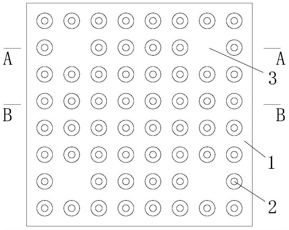
[0040] A heat storage body includes a heat storage body 1, on which a plurality of converging fluid channels 2 are opened, and the wall profile of the converging fluid channel 2 is at least two arcs and one of arcs. The bus bar formed by the tangent lines between the two turns around the central axis to form a shape or a diameter-reducing channel whose diameter changes smoothly. Like a bottleneck.

[0041] The specific structure of the diameter-reducing channel is a circular diameter-reducing channel whose diameter changes from small and smooth to larger and then from large diameter to smoothly smaller. Preferably, the bus bar is a smoothly changing streamline. Preferably, the diameter of the two ports of the converging fluid channel 2 is larger and the other is smaller, and the diameter of the converging fluid channel 2 between the large and small ports transitions smoothly from large to small. Specifically, the radius of the arc is 2-50mm, the diameter of the large port of the...

Embodiment 2

[0046] A heat storage structure in which two or more heat storage bodies are superimposed on each other as described in the first embodiment, and the two superposed heat storage bodies are connected with the convergent fluid channel 2 to form a smooth long convergent fluid aisle. Preferably, the same diameter ports of the two overlapping heat storage body converging fluid channels 2 are connected correspondingly.

[0047] The working process and working principle of the present invention: the heat storage bodies are stacked in a certain order to form a continuous streamlined or wavy long convergent fluid channel. The gas flows in the long convergent fluid channel with alternating flow velocity. Change, forming a certain turbulent vortex, the particles in the gas are not easy to deposit and block the channel, which can significantly increase the gas-solid surface heat transfer rate between the gas and the heat storage body, and because the wall of the long and narrow fluid channel...

Embodiment 3

[0050] A heat storage body forming mold for manufacturing the heat storage body described in the first embodiment, comprising an upper mold plate 4, an upper mold base 5, a convex mold 6, a lower mold base 7 and a demolding mechanism, and the lower mold base 7 The upper mold has a cavity, the upper template 4 is fixed with the upper mold base 5, the punch 6 is nested on the upper mold base 5, the molding part of the punch extends from the upper mold base 5, and the demolding mechanism is connected to the lower mold base 7. on.

[0051] Due to the large number of zoom-type fluid channels 2, it is difficult to process more punches 6 with small spacing on a steel block. Therefore, the present invention first processes the punch 6, the upper template 4 and the upper mold seat 5 separately. Then, insert the punch 6 in the upper mold base 5, and finally press the punch 6 with the upper mold 4, and fasten the upper mold 4 and the upper mold base 5 into one body with bolts, which effecti...


PUM


Abstract

The invention discloses a heat storage body and a heat storage structure of the heat storage body, a forming die and a manufacturing method. A plurality of scaling type fluid channels are formed in the heat storage body. The wall face profile of each scaling type fluid channel is of a shape formed in a mode that a busbar formed by at least two sections of circular arcs and tangent lines among the circular arcs rotates around a central shaft for a circle. Moreover, a male die of the forming die is embedded on an upper die base in a sleeved mode, and the forming portion of the male die protrudes out of the upper die base. The position, corresponding to the male die, of one end of a channel assisted forming rod of the forming die is fixed to a lower die base, the other end of the channel assisted forming rod corresponds to the male die and stretches out upwards. When the forming die is used, the end face of the male die forming portion makes contact with the end face of the extended end of the channel assisted forming rod. The scaling type fluid channels of the heat storage body change smoothly, so that the heat exchange rate is improved, basically no flow resistance is added and blocking cannot occur easily; the male die is fixed to the upper die base in an embedded and sleeved mode, so that difficulties in manufacturing dies are lowered; and it is guaranteed that the scaling type fluid channels pressed out through dies are completely through by means of the channel assisted forming rod.

Description

Technical field [0001] The invention relates to a heat storage material and a mold and method thereof, in particular to a heat storage body and a heat storage structure thereof, a forming mold and a manufacturing method. Background technique [0002] Nowadays, with the development of society, people's demand for energy is increasing. Regenerative heat exchanger is one of the effective means to recover waste heat, save fossil fuels, and reduce carbon dioxide and nitrogen oxide emissions. The key technology of the regenerative heat exchanger is the structure of the heat storage body. At present, the commonly used heat accumulators include regular heat accumulators and random heat accumulators, such as honeycomb regular heat accumulators, heat accumulator balls, etc. These heat accumulators still have many disadvantages under certain use environments, such as fluid flow. The resistance is large, the heat exchange rate is not high, and it is easy to be blocked. Therefore, not all e...

Claims


Application Information

Patent Timeline
Patent Type & Authority Applications(China)
IPC IPC(8): F28D20/00
CPCY02E60/142Y02E60/14
Inventor 冯毅
Owner SOUTH CHINA UNIV OF TECH
Learn More