Relative humidity sensor of monolithic integrated porous silicon and preparation method of humidity sensor

A relative humidity, monolithic integration technology, applied in the direction of material capacitance, etc., can solve the problems of humidity sensor not specially designed dehumidification circuit, limited product application scope and market acceptance, complicated equipment structure, etc., to eliminate external interference, price, etc. Low cost, the effect of reducing the desorption time

Active Publication Date: 2014-10-08
HEFEI UNIV OF TECH
View PDF6 Cites 4 Cited by
  • Summary
  • Abstract
  • Description
  • Claims
  • Application Information

AI Technical Summary

Problems solved by technology

[0007] The humidity sensors of the above two structures do not have a specially designed dehumidification circuit, which will cause water vapor molecules to remain in the porous silicon and affect the next measurement
If you wait for the humidity sensor to dry naturally, it will be very time-consuming; if you configure a dehumidification circuit outside the humidity sensor, it will lead to complicated equipment structure, which will limit the scope of application and market acceptance of the product

Method used


Image

  • Relative humidity sensor of monolithic integrated porous silicon and preparation method of humidity sensor
  • Relative humidity sensor of monolithic integrated porous silicon and preparation method of humidity sensor
  • Relative humidity sensor of monolithic integrated porous silicon and preparation method of humidity sensor

Examples


Embodiment Construction

[0039] specific implementation

[0040] The structural features and method steps of the present invention will now be described in detail in conjunction with the accompanying drawings.

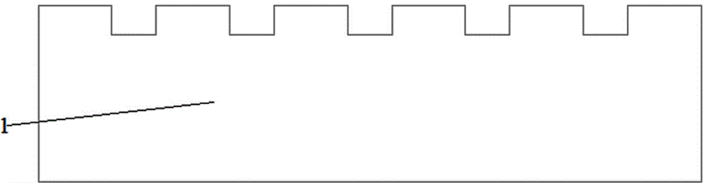
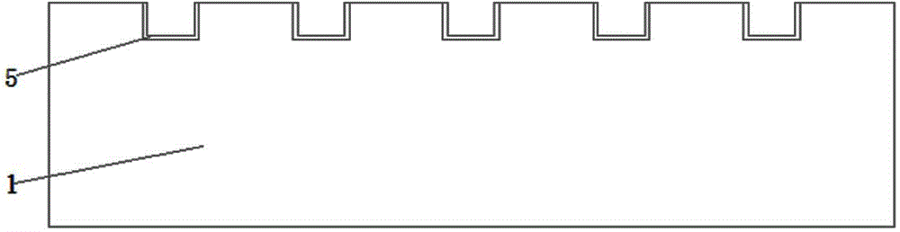
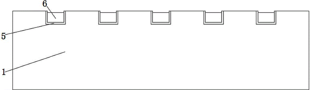
[0041] see figure 1 , a relative humidity sensor monolithically integrated porous silicon, comprising a substrate 1, the substrate 1 is a rectangular block. A pair of aluminum electrodes 6 are arranged on the top surface of the substrate 1, see figure 2 . The aluminum electrode 6 is comb-shaped, see image 3 . On the bottom surface of the aluminum electrode 6 and the side wall of the aluminum electrode 6, a layer of oxide isolation layer 5 is arranged, see figure 2 and image 3 . The top of the aluminum electrode 6 is provided with a passivation layer 4, see figure 2 . The comb teeth of the two aluminum electrodes 6 are interlaced, and the preferred solution is to arrange the comb teeth of the two aluminum electrodes 6 in an interdigitated equidistant manner. For details, see ima...


PUM

PropertyMeasurementUnit
electrical resistivityaaaaaaaaaa
thicknessaaaaaaaaaa
current densityaaaaaaaaaa

Abstract

The invention aims at solving the defect of the structure of an existing humidity sensor and provides a relative humidity sensor of monolithic integrated porous silicon and a preparation method of the humidity sensor. The humidity sensor comprises a substrate, wherein a pair of comb-shaped and staggered aluminium electrodes are arranged on the substrate; the bottom surfaces and the side walls of the aluminium electrodes are uniformly coated with oxidation isolation layers; passivation layers covers the tops of the aluminium electrodes; the top surface of the substrate at areas among combs of the aluminium electrodes is coated with a porous silicon layer; the top surface of the porous silicon layer is coated with an oxide layer; a polycrystalline silicon heating layer is arranged at the top of the oxide layer. The preparation method of the humidity sensor comprises the following eight steps: scribing, preparing an electrode tank, preparing the oxidation isolation layers, preparing the aluminium electrodes, preparing the porous silicon layer, preparing the oxide layer, preparing the passivation layers and preparing the polycrystalline silicon heating layer. The relative humidity sensor has the beneficial effects of being compact in structure and high in sensitivity; the method is compatible with an MEMS (Micro-electromechanical Systems) process; extra devices or severe working conditions are not required to be added; the method is high in yield of finished products.

Description

technical field [0001] The invention belongs to the technical field of detection equipment and relates to a monolithically integrated sensor, in particular to a monolithically integrated porous silicon relative humidity sensor and a preparation method thereof. technical background [0002] At present, humidity sensors can be divided into capacitive type, resistive type and current type according to different detection factors. Among them, the resistance-type and current-type humidity sensors are susceptible to external interference, and their detection errors are relatively large, so the capacitive-type humidity sensor is the mainstream sensor for humidity detection. From the point of view of practical application, the current capacitive humidity sensors mainly adopt ceramic type, semiconductor type, electrolyte type or organic polymer type; the humidity sensor using porous materials is still in its infancy, and most of them are small batch experiments in laboratories or fac...

Claims


Application Information

Patent Timeline
Patent Type & Authority Applications(China)
IPC IPC(8): G01N27/22
Inventor 许高斌张胜兵陈兴马渊明
Owner HEFEI UNIV OF TECH
Why Eureka
Try Eureka