Thin film solar cell production method and electrodeposition device thereof

A technology for solar cells and electrodeposition devices, applied in circuits, photovoltaic power generation, electrical components, etc., can solve the problems of reducing the effective area and affecting the conversion efficiency of light absorption, so as to reduce the contact resistance, improve the electrodeposition efficiency, and increase the contact area effect

Active Publication Date: 2014-10-08
北京恒昀动力科技有限公司
View PDF5 Cites 5 Cited by
  • Summary
  • Abstract
  • Description
  • Claims
  • Application Information

AI Technical Summary

Problems solved by technology

The filler in the groove does not participate in the photoelectric conversion process, that is, the area occupied by the contact thimble and the groove do not participate in the photoelectric conversion, and accordingly the effective area participating in the photoelectric conversion per unit area of ​​the solar cell is reduced. Affects the efficiency of light absorption conversion

Method used


Image

  • Thin film solar cell production method and electrodeposition device thereof
  • Thin film solar cell production method and electrodeposition device thereof
  • Thin film solar cell production method and electrodeposition device thereof

Examples


Embodiment 1

[0076] Figures 1a-2p Shown is the production method of the thin-film solar cell 1 described in this embodiment, comprising the following steps:

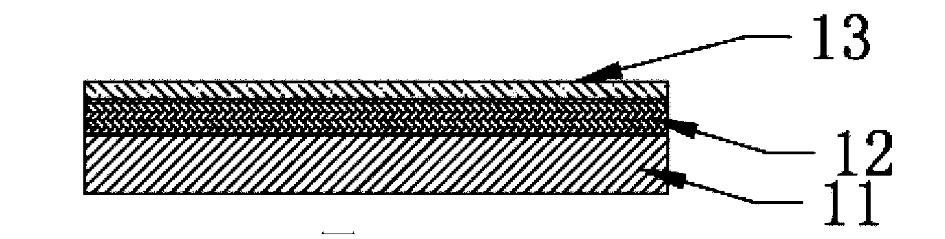
[0077] (a) Depositing a transparent conductive layer 12 (Transparent conductive oxide, TCO for short) on the glass substrate 11;

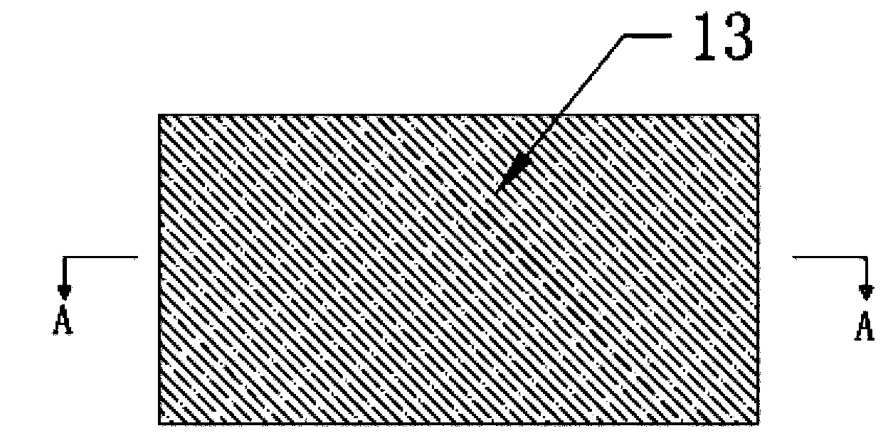
[0078] (b) forming a window layer 13 on the transparent conductive layer 12. In this embodiment, the window layer 13 is cadmium sulfide (CdS), and the window layer 13 is formed on the transparent conductive layer 12 by electrodeposition;

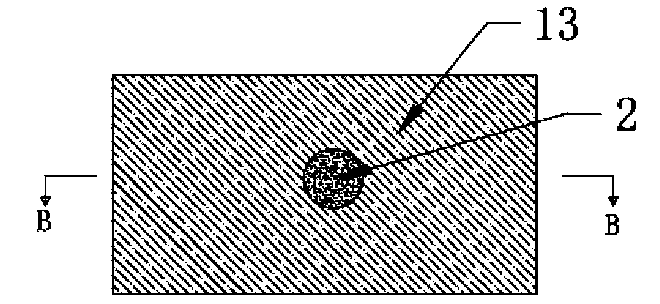
[0079] (c) The contact electrode 2 penetrates the window layer 13 and makes ohmic contact with the transparent conductive layer 12, and the above-mentioned semi-finished product is placed in the electrodeposition tank, and the contact electrode 2 and the counter electrode are energized, and the contact electrode 2 and the counter electrode are energized. Electrodeposited absorber layer 14 on 13, the absorber layer 14 is cadmium telluride (CdTe), the cross-section of t...

Embodiment 2

[0093] Figure 3a-3p Shown is a production method of a thin-film solar cell 1 described in this embodiment, including the following steps:

[0094] (a) Depositing a transparent conductive layer 12 (Transparent conductive oxide, TCO for short) on the glass substrate 11;

[0095] (b) forming a window layer 13 on the transparent conductive layer 12, the window layer 13 in this embodiment is cadmium sulfide (CdS);

[0096] (c) The contact electrode 2 penetrates the window layer 13 and makes ohmic contact with the transparent conductive layer 12, and the above-mentioned semi-finished product is placed in the electrodeposition tank, and the contact electrode 2 and the counter electrode are energized, and the contact electrode 2 and the counter electrode are energized. The absorption layer 14 is electrodeposited on 13, and the cross-section of the contact electrode 2 parallel to the glass substrate 11 in this embodiment is rectangular;

[0097] (d) Remove the contact electrode 2, a...


PUM


Abstract

The invention provides a thin film solar cell production method and an electrodeposition device thereof. The method comprises the steps that a transparent conductive layer is deposited on a glass substrate; a window layer is formed on the transparent conductive layer; an absorption layer is electrodeposited on the window layer; a contact electrode is removed, and a contact electrode gap is produced at the position of the original contact electrode; a first trench is drawn; the first trench and the remaining contact electrode gap are filled; a second trench is drawn; a back contact layer and a back electrode are deposited; a third trench is drawn; and the position of the contact electrode gap and the position of the first trench and / or the second trench and / or the third trench partially or completely overlap. According to a solar cell production device and method in the existing technology, the photoelectric conversion effective area in the unit area of a solar cell is small. According to the thin film solar cell production method and the electrodeposition device thereof, the photoelectric conversion effective area in the unit area is large.

Description

technical field [0001] The invention relates to an electrolysis device and method, in particular to a production method of a thin-film solar cell and an electrodeposition device thereof. Background technique [0002] A solar cell is a device that directly converts light energy into electrical energy through the photoelectric effect. [0003] Generally, a thin-film solar cell mainly includes a lower encapsulation layer, a base layer, a back contact layer, an absorber layer, a window layer, an upper contact layer, and an upper encapsulation layer from bottom to top. Among them, the back contact layer, absorption layer and window layer can be realized by electrodeposition; during electrodeposition, the substrate to be electrodeposited needs to be placed in the electrolyte, the transparent conductive layer of the substrate is connected to the negative electrode, and the The positive connection of the positive and negative electrodes can deposit the semiconductor compound on the...

Claims


Application Information

Patent Timeline
IPC IPC(8): H01L31/18C25D7/12
CPCC25D7/126H01L31/1836Y02E10/50Y02P70/50
Inventor 张征宇李伟中
Owner 北京恒昀动力科技有限公司
Why Eureka
Try Eureka