Supercharge Your Innovation With Domain-Expert AI Agents!

Bi-directional phase-shifted full-bridge soft switch circuit

A phase-shifting full-bridge and soft-switching technology, applied in electrical components, adjusting electrical variables, high-efficiency power electronics conversion, etc., can solve the problems of large switching loss, energy waste, hard-switching power supply frequency can not be too high, etc., to achieve low power circulation and current stress, reducing volume and quantity, and improving energy utilization

Inactive Publication Date: 2014-10-08
FUJIAN NEBULA ELECTRONICS CO LTD
View PDF4 Cites 14 Cited by
  • Summary
  • Abstract
  • Description
  • Claims
  • Application Information

AI Technical Summary

Problems solved by technology

[0003] On the one hand, based on technical and cost considerations, most of the existing battery formation charging and discharging equipment adopts a unidirectional phase-shifting power conversion structure, and the energy released during the battery discharge process is consumed through resistance discharge, resulting in extreme Large energy waste; for large-scale battery manufacturers, the electricity cost of battery formation can account for 20% to 30% of the production cost, and the annual electricity fee for formation testing is a considerable expense; in view of this problem, we are now How to reduce the consumption of discharge energy and reuse it has become an urgent problem for battery manufacturers
[0004] On the other hand, in the formation charging and discharging equipment, the phase-shifting full-bridge module adopts the traditional hard switching mode, and the switching element is turned on or off the circuit under the condition of bearing voltage or current, so when it is turned on and off In the process, a large switching loss will be generated, and the higher the switching frequency, the greater the switching loss; at the same time, the oscillation of the distributed inductance and parasitic capacitance of the circuit will be aroused during the switching process, which will bring additional loss and generate electromagnetic interference. Therefore, the frequency of the hard-switching power supply cannot be too high, and measures to prevent electromagnetic interference must be taken. The EMI characteristics are poor and the efficiency is low, and its power switching elements work in the hard-switching mode, and the switching loss is large. It is difficult to increase the power density through high frequency
During the operation of the power switch circuit, the upper and lower tubes are prone to accidents, and the safety factor is not high.

Method used


Image

  • Bi-directional phase-shifted full-bridge soft switch circuit
  • Bi-directional phase-shifted full-bridge soft switch circuit

Examples


Embodiment Construction

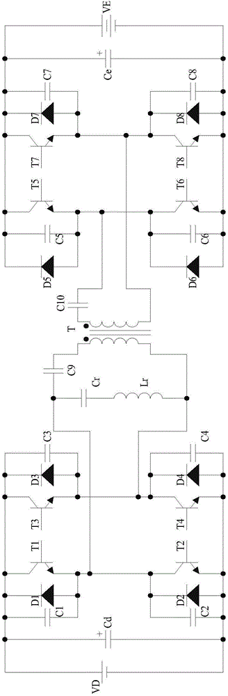
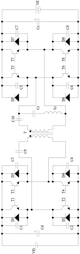
[0016] see figure 1 and figure 2 As shown, the bidirectional phase-shifting full-bridge soft switch circuit of the present invention includes a transformer T, a first bidirectional phase-shifting full-bridge circuit, a second bidirectional phase-shifting full-bridge circuit and a resonant circuit, and the transformer T is respectively connected to the The first bidirectional phase-shifting full-bridge circuit and the second bidirectional phase-shifting full-bridge circuit.

[0017] The resonant circuit in the present invention includes a DC blocking capacitor C9, a DC blocking capacitor C10, a resonant inductance Lr and a resonant capacitor Cr, and the resonant inductance Lr is connected in series with the resonant capacitor Cr;

[0018] The first bidirectional phase-shifting full-bridge circuit includes a switching tube T1, a switching tube T2, a switching tube T3 and a switching tube T4, the switching tube T1 and the switching tube T2 are connected in series to form a firs...


PUM


Abstract

The invention provides a bi-directional phase-shifted full-bridge soft switch circuit which comprises a transformer T, a first bi-directional phase-shifted full-bridge circuit, a second bi-directional phase-shifted full-bridge circuit and a resonance circuit. The transformer T is respectively connected with the first bi-directional phase-shifted full-bridge circuit and the second bi-directional phase-shifted full-bridge circuit through the resonance circuit. Power consumption is reduced, and the safety coefficient is increased.

Description

technical field [0001] The invention relates to a bidirectional phase-shifting full-bridge soft switch circuit. Background technique [0002] An indispensable process in the lithium battery production process is formation, which is to charge and discharge the battery twice. The charging and discharging technology of the formation power supply equipment directly affects the performance and use of the battery. [0003] On the one hand, based on technical and cost considerations, most of the existing battery formation charging and discharging equipment adopts a unidirectional phase-shifting power conversion structure, and the energy released during the battery discharge process is consumed through resistance discharge, resulting in extreme Large energy waste; for large-scale battery manufacturers, the electricity cost of battery formation can account for 20% to 30% of the production cost, and the annual electricity fee for formation testing is a considerable expense; in view of...

Claims


Application Information

Patent Timeline
Patent Type & Authority Applications(China)
IPC IPC(8): H02M3/28H02M3/335H02M1/36
CPCY02B70/10
Inventor 李有财易军生林志雄范俊
Owner FUJIAN NEBULA ELECTRONICS CO LTD
Features
  • R&D
  • Intellectual Property
  • Life Sciences
  • Materials
  • Tech Scout
  • Unparalleled Data Quality
  • Higher Quality Content
  • 60% Fewer Hallucinations
Learn More